8-2 BL-E30-0515 - 07-27-2016
8-1.2. Repair
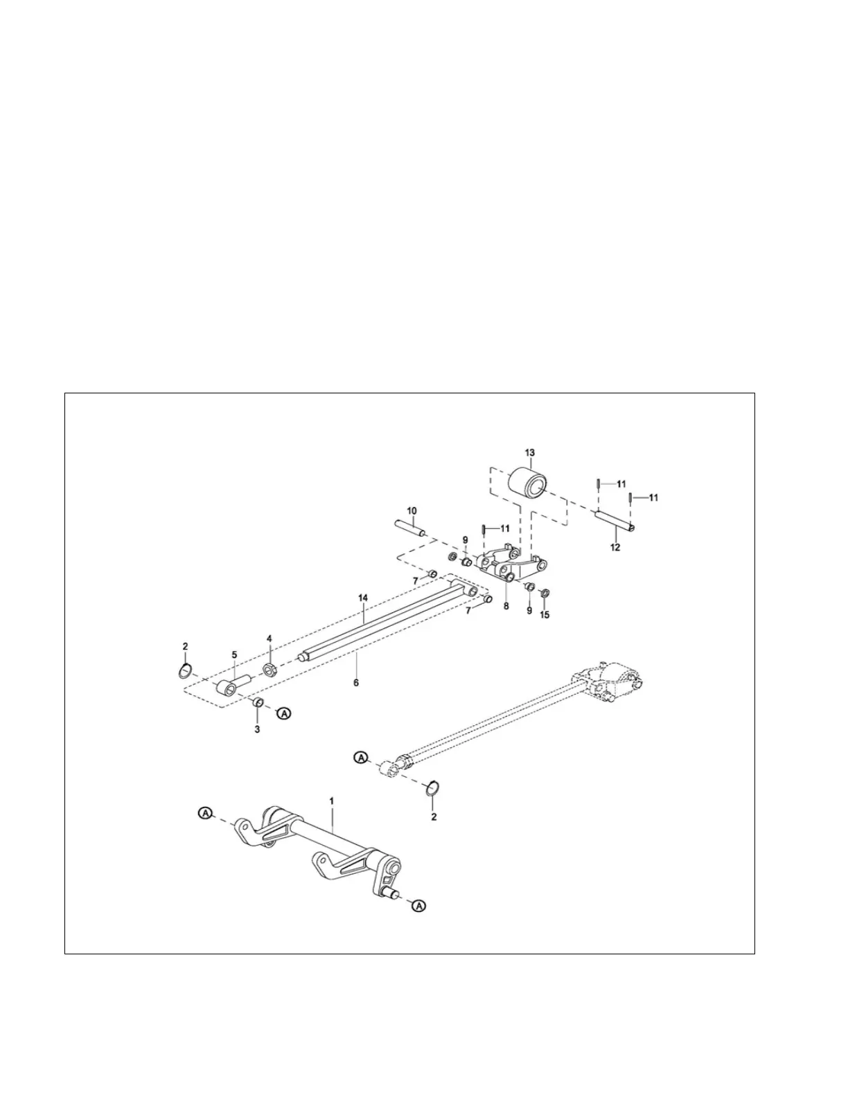
1. Remove pins (11, Figure 8-2), shafts (12) and
load wheel (13) from wheel brackets (8).
2. Remove pins (11) and shafts (10). Free brackets
(8) from tension bars (6).
3. Remove bushings (9) from brackets (8) if replace-
ment is necessary,
4. Remove clips (2) from link (1) and free tension
bars from link (1).
5. Loosen nuts (4) and remove clevises (5) from ten-
sion bars (6).
6. Remove bushings (3) from clevises (5) if replace-
ment is necessary.
7. Install reassemble by reversing the steps above.
8-1.3. Installation
1. Position link assembly under frame (8, Figure 8-
1).
2. Raise each link assembly (14, Figure 8-2) into
position and install shaft (9, Figure 8-1) through
frame (8). Secure shaft (9) with clips (3).
3. Position wheel brackets (8, Figure 8-2) in frame
(8, Figure 8-1) and install shafts (6). Secure shafts
(6) with pins (7).
4. Position link assembly (14) and install shafts (10).
Secure shafts (10) with pins (11),
5. Remove blocking and lower the truck to the
ground.
6. Turn on the key switch (20, Figure 12-18) and
emergency disconnect (17).
Figure 8-2 Lift Linkage Assembly