COMBIMASS
®
compact
Doc. No.: 0905ME20500 18
Chapter 2 Installation
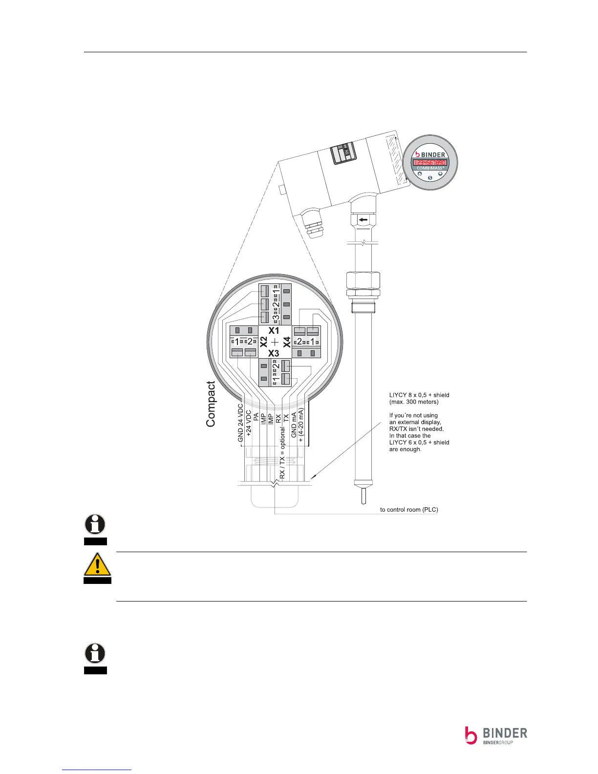
Wiring of the sensor electronic for field unit
Protection class: IP65und EEx [ed]
Diagram: Wiring of the sensor for field unit
Bridge „X1(1) - X4(1) is necessary if you only use the RX/TX-signal
(otherwise GND is missing [X4.(1)]).
In the case of "Ex" explosion-proof versions of the device, use only the "Ex (d)" explosion-proof scre-
wed gland offered/supplied by us. Screwed glands in IP 65 and "EEx d" must be sealed in the con-
necting head with suitable sealing material. In the case of combustible gases, a leak will give rise to a
fire or explosion hazard.
The wiring is completed in accordance with the diagram using a simple shielded cable up to 300 meters
in length, and with min. 6x 0.5 mm
2
. The cable shielding is connected in the sensor head.
■ Cable type: LIYCY 8 x 0.5 mm
2
+ shield (or LIYCY 6 x 0.5 mm
2
+ shield if you don't use RX/TX)
■ The cable is not suitable for laying underground.
■ The cable does not have long-term resistance to ultra-violet (UV) radiation.
NOTE
DANGER
NOTE
In a system without field housing, the wires di-
rectly connect from the electronic enclosure to
the control room