Installation
9
Connecting the Wideband Power Sensor (WPS)
1. Do one of the following:
Connect the DPM port on the Bird WPS to the “Sensor” serial port on
the DPM using the sensor cable provided.
Connect the DPM port on the Bird WPS to the “Sensor” USB port on the
DPM using the sensor cable provided.
2. Connect the WPS to the RF line so that the arrow on the sensor points
towards the load.
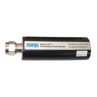
Connecting the Terminating Power Sensor (TPS)
Note: Connections are the same for the Bird 5011 and 5011-EF.
1. Do one of the following:
Connect the DPM port on the Bird TPS to the “Sensor” serial port on
the DPM using the sensor cable provided.
Connect the DPM port on the Bird TPS to the “Sensor” USB port on the
DPM using the sensor cable provided.
Note: An attenuator or directional coupler should be used with
the TPS in most applications.
Example - For an RF source with output between 0.1 and
50 W, use a 40 dB, 50 W attenuator.
2. Connect the TPS RF input to the source (using an attenuator, if
appropriate).
Note: Only connect the TPS directly to a source if the RF power
will be less than 10 mW.
CAUTION
Discharge all static potentials before connecting the TPS(-EF). Electrostatic
shock could damage the sensor.
CAUTION
When connecting the TPS or the TPS-EF, only turn the connector nut. Damage
may occur if torque is applied to the sensor body.
CAUTION
Do not exceed 2 W average or 125 W peak power for 5 s when using the TPS
or the TPS-EF. Doing so will render the sensor inoperative.