6
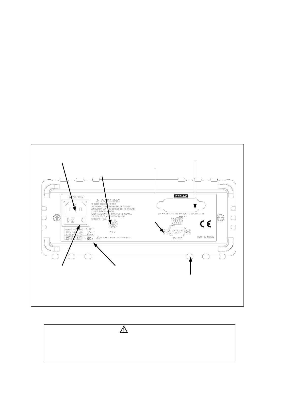
The rear panel (shown in Figure 2-2) contains a line fuse, the power-line
cord connector, an RS-232 interface connector, and a cutout for IEEE-488
interface (optional) connector.
! Line Power
! Figure 2-2 illustrates the location of the Line Voltage Selector with Fuse
Holder housing. If user has already done so, plug the line cord into the
connector on the rear of the meter. The meter will operate at any line
voltage between 90Vac and 264Vac when “line voltage selector” is set
properly, and its frequency range is at 50/60Hz. For operation safety, DO
NOT APPLY a line voltage that exceeds the range specified to line cord
connector on the rear panel of the meter.
Figure 2-2. Rear Panel
CAUTION!
BEFORE TURNING THE METER ON, MAKE SURE THE LINE VOLTAGE
SELECTOR IS SET TO THE CORRECT POSITION FOR APPLIED LINE
VOLTAGE TO THE POWER-LINE CORD CONNECTOR.
Line Voltage Selector with
Fuse Holder Housing
Line Voltage Fuse
Selection Table
Power-Line Cord Connector
RS-232 Connector
IEEE-488 I/F Connector *
*Available with IEEE-488 Interface Option only.
Otherwise covered with Plastic Decal.
Earth Ground Terminal Screw
Real Panel
Protective Holster