47
5. Use the numeric keypad or rotary knob to enter the values for Range, Voltage High,
Voltage Low, and Vd. Vd will be the forward voltage of the LED you want to simulate.
This option will only appear after CR_LED has been enabled from the CONFIG menu.
6. While in CR mode, use the numeric keypad or rotary knob to enter a value for Rd, the
resistance.
7. Now that both Vd and Rd are configured, turn ON the input by pressing .
Remote Sense
Remote sense can be used to compensate for voltage drops (up to 1 V) due to resistance from
test leads connected to your device under test (DUT), thus providing more accurate voltage
measurement. The instrument is setup with remote sense disabled by default.
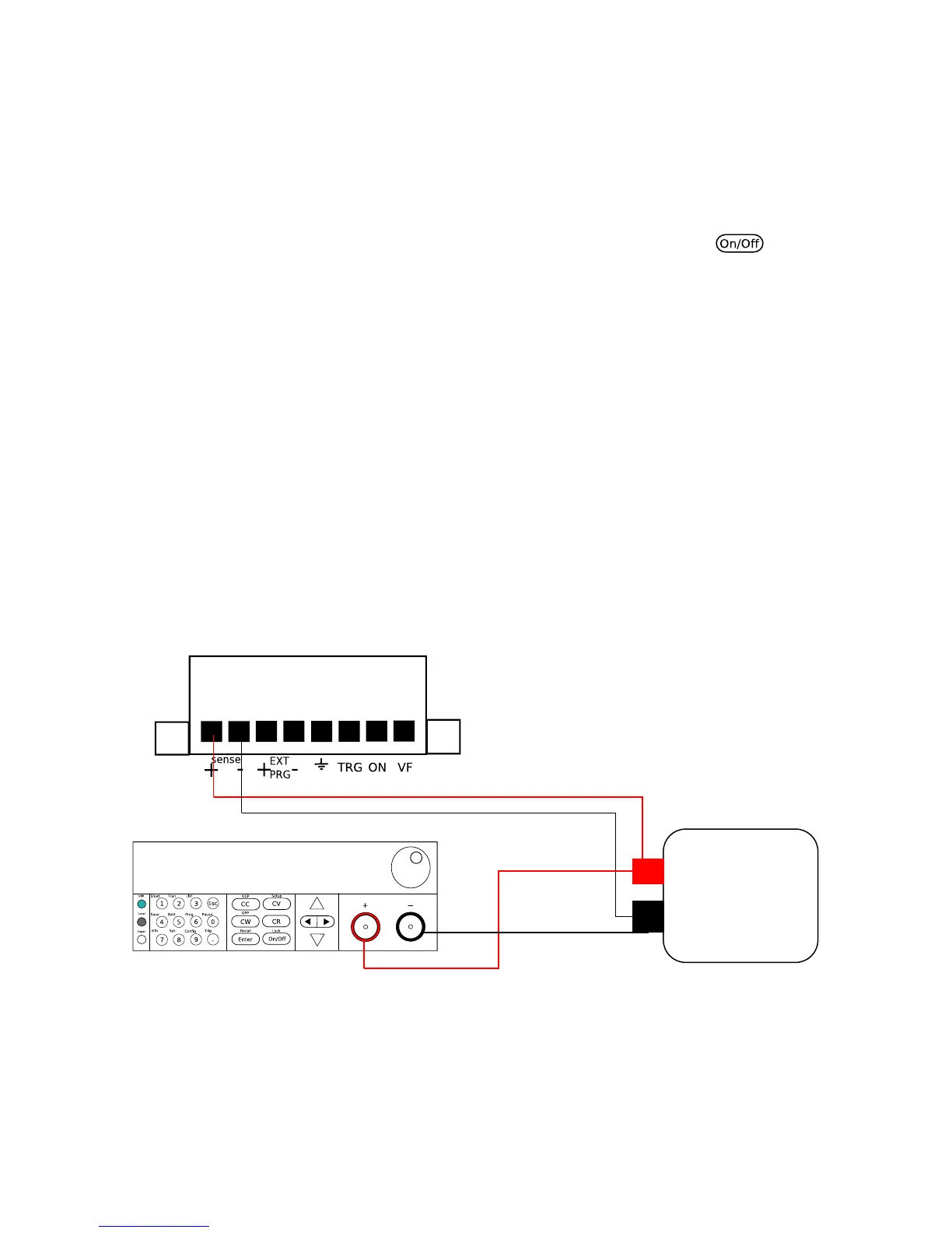
To enable and use remote sense, follow the steps below:
1. Power OFF the load and disconnect all leads/cables connected to it.
2. Connect the sense terminals in the rear panel to the DUT source terminals.
3. Then, connect the DUT source terminals to the load’s main input terminals. The setup
should look like the figure below:
Figure 18 - Remote Sense Connection Setup