10
User's Manual
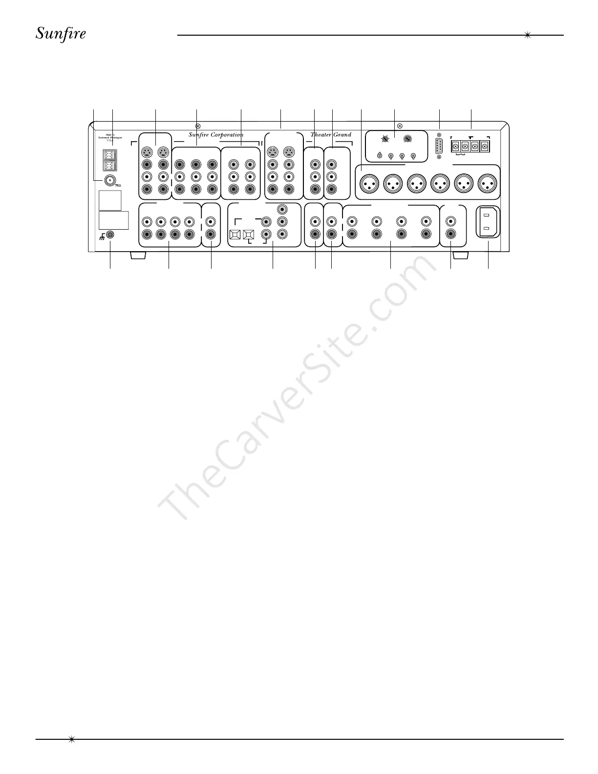
Rear Panel Features
A
M
G
N
D
F
M
SIGNAL
GROUND
LEFT
RIGHT
AUDIO
LEFT
AUDIO
COMPOSITE
VIDEO
S VIDEO
CD
MONITOR
VCRUSE EITHER OR BOTH
DAT/TAPE
VCR VAUX 1
VAUX 2
DBS/BS
LEFT
FRONT
CENTER
RS-232
12VDC TRIG.
VIDEO FUNCTION
RELAY
CLOSED
WHEN ACTIVE
FIFTY
MILLIAMPS
MAIN
LARGE
SMALL
CENTER
OFF
ON
SURROUND
OFF
ON
SUB
OFF
ON
RIGHT
FRONT
LEFT
SURROUND
RIGHT
SURROUND
SUB
WOOFER
LEFT
RIGHT
V
I
D
E
O
C
O
M
P
O
S
I
T
E
S
L
R
COMPONENT
COMPONENT
OUT
MAIN
RECORD
OUT
LD/DVD
PHONO
TAPE
EXTERNAL
PROCESSOR
IN
VCR
CD
DAT/
TAPE
TAPE
OUT
FRONT
MAINS
SUB 1 SUB 3
REAR
SURROUND
CENTER
SUB 2 SIDES
120 VAC
60Hz
NOMINAL
0.40 AMPERES
EXTERNAL
PROCESSOR
OUT
RIGHT
LD/DVD
DBS/BS
L
R
L
R
DBS/BS
LD/DVD
R
L
BY
RY
Y
BY
RY
Y
BALANCED AUDIO OUTPUTS
L
R
MAIN AUDIO OUTPUTS
SEVEN
AXIS
MAIN MONITOR
OUTPUTS
AUDIO VIDEO INPUTS
AUDIO VIDEO
OUTPUTS
AUDIO INPUTS
DIGITAL AUDIO
INPUTS
COMPOSITE
VIDEO
05ms
CENTER DELAY
SURROUND DELAY
015ms
510
MANUFACTURE D UNDE R LICENS E
FROM DIGITAL THEATER SYSTEMS,
INC. U.S. PAT. NO. 5,451,942 AND
OTHER WORLD-WIDE PAT ENTS
ISSUED AND PENDING. "DTS", "D
TS
DIGITAL SURR OUND", ARE
TRA DEMAR KS OF DIGITAL
THE ATER SYSTEM S, INC.
COPYRIGHT 1996 DIGITAL THEATER
SYSTE MS, INC. ALL RIGHTS
RESERVED.
–+
R
L
R
L
MANUFACT URED UNDER
LICENSE FROM DOLBY
LABORATORIES. "DOLBY",
"PRO-LOGIC' AND TH E
DOUBLE-D SYMBO L ARE
TRADEMARKS OF DOL BY
L A B O R A T O R IES .
CON FIDE N T IAL
UNPUB LISHED WOR KS.
©1 992-1997 DOLBY
LABORATORIES, INC. ALL
RIGHTS RESERVED.
12 3 4 5 6 78 9 10 11 12
181716151413 19 20 21
1. FM Antenna Connection
The supplied FM antenna fits over the
inner pin of this “F-type” push-on connector.
Other antennas can be fitted if you have a
suitable adaptor.
2. AM Antenna Connection
This is a spring-loaded connection for the
AM loop antenna. Other antennas can be
fitted, including larger diameter loop designs.
3. DBS/BS and LD/DVD Inputs
These audio, composite-video and S-video
inputs connect to the outputs of your DBS/BS or
LD/DVD. When these inputs are selected, the
audio will be heard in your system and the video
will be seen on the TV screen.
4. VCR, VAUX1 and VAUX2 Inputs
These audio and composite-video inputs
connect to the outputs of your VCR machines.
If the VCR input is selected, the audio will be
heard in your system and the video will be seen
on the TV screen.
Note: There is no VAUX2 input selector on
the front panel or remote. If VAUX1 is selected,
the Processor will automatically select either
VAUX1 or VAUX2, whichever one is playing. If
both VAUX1 and VAUX2 are connected, make
sure that only one machine is playing at a time,
otherwise the wrong one may be selected.
5. Component Video Inputs
These component-video inputs connect to
the outputs of your DBS/BS or LD/DVD.
When these inputs are selected, the Proces-
sor will automatically route the video signals
going into these jacks to the component video
output (see #7).
6. Main Monitor Outputs
These audio, composite-video and S-video
outputs connect to the corresponding audio
and video inputs of your TV Monitor.
7. Component Video Outputs
These connect to the component video
inputs of your TV monitor. The Processor will
switch the component video signals from any
video equipment connected in #5.
8. VCR Record Outputs
These connect to the inputs of your VCR
to allow recording of the selected input.
9. Balanced XLR Audio Outputs
These connect to the balanced XLR
inputs of your amplifier. If your amplifier has a
choice of inputs, we recommend using the
XLR type for better noise rejection.
Rear Panel Features