Home
BobsCNC
Industrial Equipment
Evolution Series
Page 49
BobsCNC Evolution Series - Page 49
156 pages
Manual
Save Page as PDF
To Next Page
To Next Page
To Previous Page
To Previous Page
Loading...
48
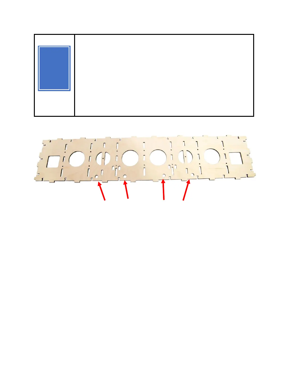
Prior to putting the Gantry Assembly together,
note that the four ½” (12mm) hol
es at the
bottom of the Gantry Frame (G1) must be
oriented on the bottom of the Gantry
Assembly. They provide access to adjust the
Y Carriage Bearings in a later step.
Bearing Adjustment Access Holes
TIP
T
48
50
Table of Contents
Main Page
Table of Contents
3
Information/Warning Boxes
6
Safety Precautions and Warnings
7
Getting Started
8
Required Tools
8
To Operate the EVOLUTION 5 CNC Router, You Need will Need
8
Recommended for the Electronic Setup Include
8
Assembly Recommendations
9
Z Spindle Mount Assembly
10
Required Wood Components
10
Required Hardware
12
Illustrated Step by Step Instructions
13
Y Carriage Assembly
25
Required Wood Components
25
Required Hardware
26
Illustrated Step by Step Instructions
34
Gantry Assembly
42
Required Wood Components
42
Required Hardware
43
Illustrated Step by Step Instructions
46
Front View (Right Hand Side) Completed
60
Frame Instructions
85
Required Wood Components
85
Required Hardware
86
Illustrated Step by Step Instructions
87
Final Assembly
105
Wood Components (Included with Kit)
105
Required Hardware
105
Illustrated Step by Step Instructions
107
T-Slot Spoilboard
139
Wood Components
139
Required Hardware
139
Completed Views
146
Tramming
151
Clamping System
153
Wood Components (Included with Kit)
153
Required Hardware
153
Congratulations! You Just Completed the Assembly of Your Evolution 5
154
Updating Firmware
154
Evolution 5 Firmware Value Change
154
Appendix ($130=1283)
155
Evolution 5 Firmware Values
155
Evolution Washer Dimensions
156
Related product manuals
BobsCNC QUANTUM MINI
138 pages