50
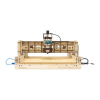
Step 8 Align and insert the tabs of the Gantry Frame Assembly into the
slots in the Gantry Bottom Brace (G9) and secure with fifteen
M4 x 16 Machine Screws and Nuts as shown. NOTE: The
Bearing Adjustment Access Holes in the Gantry Frame are at
the bottom.
Step 9 Align and insert the tabs of the Gantry Back Support (G8) into
the slots of the Gantry Frame Assembly and secure with two M4
x 16 Machine Screws and Nuts. Repeat at the opposite end of
the Gantry as shown.
Left Side Right Side