35
OK
OK
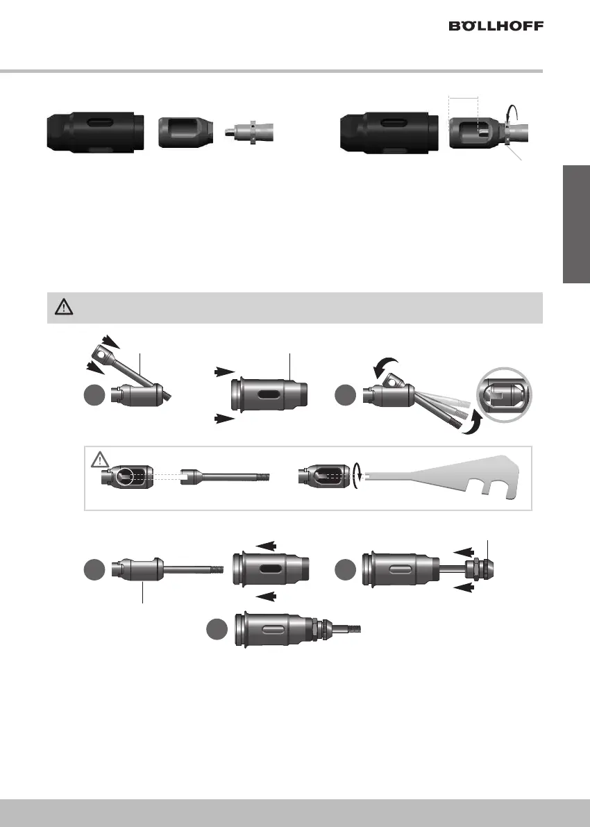
1. Adjust roughly a distance of 22,5 mm between the front side of the fork and the driveshaft.
2. Then, install the mandrel and test to optimise the position of the fork:
• Always ensure the installation/remove of the mandrel
• Reduce as much as possible the axial mechanical clearance of the mandrel inside the fork
3. Tighten the counter nut for fixing the position with a torque of 10Nm.
• Remove the mandrel
• Refit the new mandrel
! by taking care to align the back side groove with the screwing driver
(see in figure 4).
CAREFULL: grease (Multipurpose grease) has to be applyed between fork
# and mandrel !.
• Reposition the nose
"
• Retighten the nose " to 15 Nm.
• Screw the new anvil
$ inside the nose and lock it after adjusting the correct position thanks
to the nut.
THE BATTERY HAS TO BE DISCONNECTED WHEN REPLACING THE TOOLING.
MANDREL (1) MOVES DURING USE. AVOID CONTACT AND PAY THE UTMOST ATTENTION.
! "
#
$
OK
Mandrel Nose
Fork
Anvil
Figure 4 - Mandrel alignement
A
C D
E
B
Figure 3 - Fork and nose for studs & force >18 kN (M8 & M10)
(22,0 —> 24,0 mm)
Force: 10 Nm
<>
Pos. 23616600213
English