EM-RES-03 1310/07
Control terminal X410A
Ter. Description
1 DC-24 V output (max. 180 mA)
1)
2 Ground 24 V
3 Digital output EM-S1OUTD
2)
4 Digital output EM-S2OUTD
2)
5 Not connected
6 Analog input EM-S1INA
2)
7 Ground 10 V
Control terminal X410B
Ter. Description
1 Not connected
2 Digital input EM-S1IND
2)
3 Digital input EM-S2IND
2)
4 Digital input EM-S3IND
2)
5 System bus, CAN-Low
6 System bus, CAN-High
7 Ground
1)
The power supply at terminal X410A.1 may be loaded with a maximum current of
I
max
= 180 mA. Relative to the application, the maximum current available will be
reduced by the further control outputs of the frequency inverter and expansion
module.
2)
The control electronics is freely programmable.
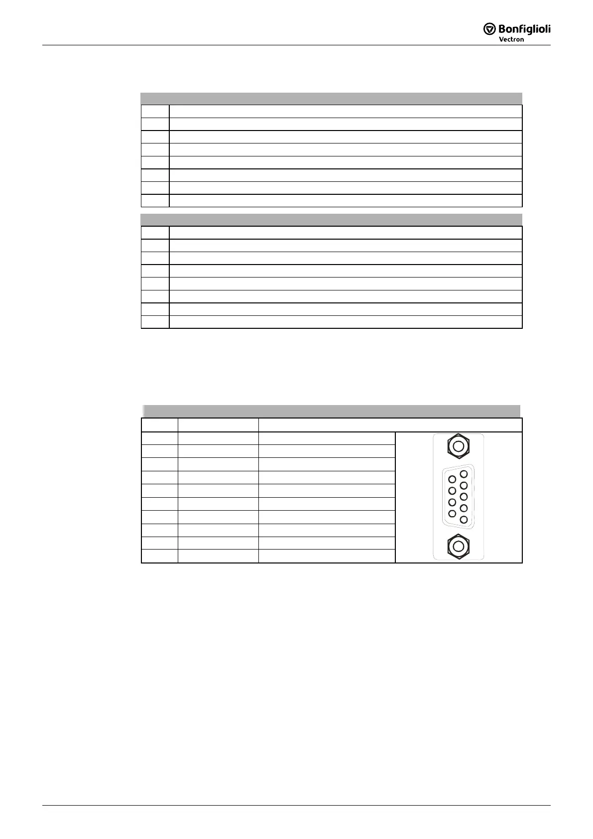
Resolver- and PTC input (SubD-9)
Pin Designation Function
socket shielding Connected with PE
1 PE Protective earth conductor
2 PTC+ PTC thermistor connection
3 COS+ Cosinus track
4 SIN+ Sinus track
5 +UE Excitation voltage
6
PTC-
PTC thermistor connection
7
COS-
Cosinus track
8 SIN- Sinus track
9
-UE
Excitation voltage
1
9
5
6
Note: If a synchronous motor should be connected to the resolver input which is
not from BONFIGLIOLI it can be necessary to change the sign of the sinus
track. This can be set via parameter
Evaluation Mode 492. Refer to chapter
6.4.3.
• Use PTC thermistors with safe insulation from the motor winding acc. to
EN 61800-5-1.
• Use shielded twisted pair.
• The resolver cable must be kept physically separate from the motor cable.
• Place the cable shield of the resolver cable on both sides with large area contact.
• BONFIGLIOLI VECTRON recommends ready-made cable for the connection of
synchronous motors of types BCR and BTD.

 Loading...