EM-RES-03 10/0712
D
Communication interface system bus
CAN actuation of the system bus according to ISO-DIS 11898 (CAN High Speed)
E
Resolver- and PTC thermistor input (SubD9)
he resolver interface is suitable for the connection of standard resolvers with the
following specifications:
Input impedance > 95 Ω at 8 kHz, number of pole pairs up to 7,
30 000 rpm at number of pole pairs = 1
Excitation voltage U
REF
rms
= 3.5 V, I
max
= 60 mA
Input voltage U
min
rms
= 1.8 V, voltage proof up to 30 V
Phase shift (at excitation frequency): 7° (5 kHz), 14° (10 kHz), 26° (20 kHz)
Tripping resistance > 2.4 kΩ (PTC) acc. DIN 44081,
PTC thermistor or bimetal temperature sensor (normally closed contact)
Use PTC thermistors with safe insulation from the motor windin
acc. to
EN 61800 5-1.
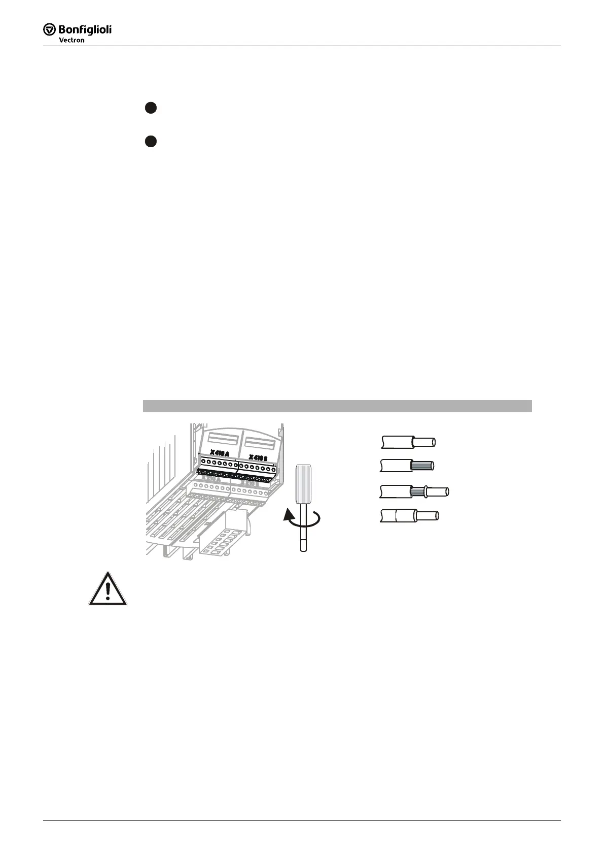
4.3.2 Control terminals
The control and software functionality can be freely configured for economical opera-
tion with a safe function.
Expansion module EM-RES-03
0.14 … 1.5 mm
AWG 30 … 16
2
Wieland DST85 / RM3,5
0.14 … 1.5 mm
AWG 30 … 16
2
0.25 … 1.0 mm
AWG 22 … 18
2
0.25 … 0.75 mm
AWG 22 … 20
2
0.2 … 0.3 Nm
1.8 … 2.7 lb-in
Caution! The control inputs and outputs must be connected and disconnected free
of electrical power. Otherwise components may be damaged.
Attention! In order to minimize electromagnetic interference and to obtain a good
signal quality, the line screen is to be connected to PE on a plane at both
ends.

 Loading...