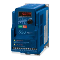
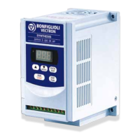
Do you have a question about the BONFIGLIOLI Vectron and is the answer not in the manual?
Describes fundamental steps for mechanical and electrical installation.
Documents complete functionality, parameters, and additional functions.
Supplements documentation for installation and commissioning, describing application-specific subjects.
Describes mechanical installation and use of devices differing from brief/operating instructions.
Provides general information about BONFIGLIOLI VECTRON frequency inverters and safety precautions.
Details the intended use of frequency inverters in industrial plants and machines, and compliance with directives.
Provides guidelines for proper transport and storage of units in dry rooms with specific climatic conditions.
Emphasizes careful handling to avoid damage and injury, and adherence to directives and standards.
Instructs to de-energize the inverter before connection work and comply with standards and directives.
Details pre-commissioning steps, cover checks, and socket verification.
Warns against unauthorized opening and states repairs must be done by authorized personnel.
Lists the connections and functions for Terminal X410A.
Lists the connections and functions for Terminal X410B.
Details specifications for the Resolver and PTC input, including impedance, voltage, and resistance.
Provides technical data for digital inputs, digital outputs, analog input, and DC-24V output terminals.
States installation must be by qualified personnel according to directives and that EMI must be avoided.
Details safety precautions for mechanical installation, emphasizing de-energizing the unit.
Warns of danger from electrical current and potential destruction if instructions are not followed.
Presents the circuit diagram for terminals X410A, X410B, and X412, detailing connections.
Details CAN actuation of the system bus according to ISO-DIS 11898.
Specifies requirements for connecting standard resolvers, including impedance and pole pairs.
Explains that control and software functionality can be freely configured for economical and safe operation.
Lists terminal connections and their descriptions for X410A.
Lists terminal connections and their descriptions for X410B.
Details pin assignments, designations, and functions for the resolver and PTC input.
Explains how to activate bus termination using DIP switch S1 for the first and last nodes.
Specifies using twisted cable with harness shield and separating control/communication lines from power lines.
Details the connection of the system bus via sockets of plug X410B.
Explains baud rate setting must be identical for all subscribers and depends on line length.
Details how to set the system bus node ID using parameter Node-ID 900 for up to 63 slaves.
Explains the physical connection and logical communication channels via identifiers.
Controls subscriber start/stop, generates boot-up reports, and handles fault reports via NMT telegrams.
Describes two SDO channels for parameter data exchange, with one master per channel.
Details three PDO channels for process data exchange, with time or SYNC control options.
Explains the Minimum Capability Boot-Up method for state control and the use of Boot-Up Delay parameter.
Details the generation of SYNC telegrams by the master for synchronous PDOs and identifier settings.
Explains how slaves transmit emergency telegrams on fault and how the master reacts.
Explains how subscribers are addressed and parameterized via SDO channels by the master.
Covers boot-up messages and status control commands for slaves.
Explains the boot-up telegram transmission and its importance for PLC/PC masters.
Details NMT telegrams for controlling slave states like Start Remote Node, Enter Pre-Operational, etc.
Explains processing of SYNC telegrams for synchronous PDOs and identifier settings.
Explains emergency telegram transmission on fault switch-off and data content.
Details the two server SDO channels for parameter data and visualization tools.
Describes SDO Segment Protocol Expedited for data exchange and telegram formats for writing/reading parameters.
Explains accessing subscribers via field bus interface using SDO1.
Details Profibus-DP object communication for system bus subscriber access.
Describes telegram structure for RS232/RS485 communication using VECTRON bus protocol.
Details PDO channel definition via identifiers according to CANopen Predefined Connection Set.
Describes time-controlled or SYNC-controlled transmit/receive behavior for PDO channels.
Explains monitoring of received data against defined time windows for SYNC telegram and RxPDO channels.
Describes defining communication relationships for PDO channels via identifier assignment.
Explains mapping of objects into PDO telegram data bytes using sources and links.
Details parameters used to specify data for transmission in TxPDO telegrams.
Explains how received data from RxPDOs is displayed via sources or source numbers for use in local input links.
Provides examples of connecting frequency inverters and using virtual links for synchronous operation.
Details using XPI files for system bus parameter configuration and access.
Explains planning and documenting communication relationships using a table.
Details planning and documenting virtual links using a table.
Explains capacity planning based on PDO telegram content, baud rate, and transmission interval.
Details the configuration and parameterization of the analog input signal.
Details analog input configuration as voltage or current, and parameterization of input signal.
Describes mapping analog input signals to reference values using linear characteristic points.
Explains how operation modes scale analog input signals based on characteristic points.
Shows examples of analog voltage signal operation modes and their effects on characteristic mapping.
Maps analog input signals to configurable characteristics using frequency or percentage limits.
Explains adapting analog input characteristic with tolerance band for zero crossing and hysteresis.
Configures monitoring of analog input signal for error and warning conditions.
Details adjusting the analog input due to component tolerances using parameter Adjustment 568.
Sets the time constant for filtering the reference analog value to eliminate faults.
Describes parameterization of digital outputs for linking to various functions.
Explains digital output parameterization links outputs to functions based on configuration.
Selects operation modes for digital outputs EM-S1OUTD and EM-S2OUTD.
Explains using fixed frequencies as reference values and extended functionality for switch-over.
Details three digital inputs and their assignment to software functions based on configuration.
Explains using the resolver input for position information and setting the field signal frequency.
Details adjusting the offset for precise rotor position detection and true running.
Explains selecting the actual speed source for the speed controller via Actual Speed Source 766.
Describes changing the sign of the sinus track for non-BONFIGLIOLI synchronous motors.
Connects functions to reference values via frequency or percentage reference channels.
Explains reading actual speed sensor values and displaying analog input signals.
Explains reading digital signal status in decimal coding and converting to binary system.
Describes temperature monitoring using PTC or bimetal sensors and configurable error/warning behavior.
Lists actual values for machine and frequency inverter parameters with units, display ranges, and chapters.
Lists parameters by category (Resolver, Digital outputs, Analog input, Speed controller, System bus) with settings and chapters.
Lists system bus parameters like Node-ID, Baud-Rate, Boot-Up Delay, SYNC identifiers, SDO/PDO identifiers, and functions.
Documents failure keys related to control connections, such as resolver synchronization and pole pair number issues.
| Communication | CANopen |
|---|---|
| Protection | Overcurrent, Overvoltage, Overtemperature |
| Storage Temperature | +70°C |
| Humidity | 95% RH, non-condensing |
| Enclosure Rating | IP20 |
| Input Voltage | 24 V DC |


 Loading...