EM-RES-03 1510/07
5.2 Cables
For the bus line, use twisted a cable with harness shield (no foil shield).
Attention: The control and communication lines are to be laid physically separate
from the power lines. The harness screen of the data lines is to be con-
nected to ground (PE) on both sides on a large area and with good con-
ductivity.
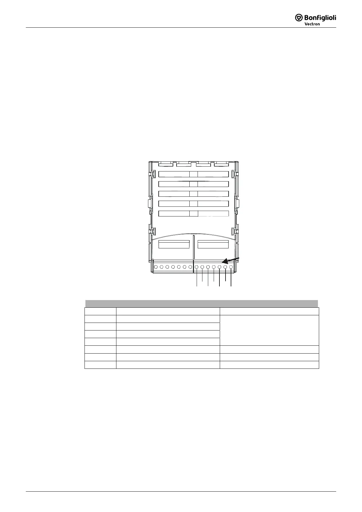
5.3 Socket X410B
The system bus is connected via three sockets of the plug X410B on the EM-RES-03
expansion module.
X410A
410B
1
2
4
3
5
6
7
1
2
4
3
5
6
7
410B
Socket X410B
Socket Input/Output Description
X410B.1 Not connected
X410B.2 Digital input S1IND
X410B.3 Digital input S2IND
X410B.4 Digital input S3IND
Chapter
„Control inputs and outputs“
X410B.5 CAN-Low CAN-Low (System bus)
X410B.6 CAN-High CAN-High (System bus)
X410B.7 GND CAN-GND (System bus)

 Loading...