EM-RES-03 5310/07
6.1.3 Operation modes
The operation modes of the analog input characteristic enable application-related scal-
in
as a supplement to the characteristic points stated. One of the four linear types o
characteristic is selected for adaptation of the si
nal for the analo
input si
nal via the
parameter
Operation mode 562.
If the characteristic points are not suited for the type of characteristic selected, the
characteristic points are corrected internally.
Operation mode Function
1 - bipolar The analog input signal is mapped onto the reference
figure according to the characteristic points (X1/Y1)
and (X2/Y2).
11 - unipolar With a negative parameter value of the characteristic
points X1 or X2, they are mapped to the reference
value zero.
21 - unipolar
2…10 V / 4…20 mA
If the characteristic points X1 or X2 have been set
with a negative parameter figure or smaller than 0%,
the input characteristic is mapped to the reference
value 20%.
101 - bipolar absolute value Negative parameter values of the characteristic points
Y1 or Y2 are mapped as a positive reference value in
the characteristic.
Further information on the operation modes stated in the table can be found in the
following chapter "Examples“.
6.1.3.1 Examples
The analog input signal is mapped onto a reference value as a function of the charac-
teristic. The following examples show the operation modes for an analog voltage sig-
nal. The parameter
Minimum Frequency 418 is set to the value 0.00 Hz. The charac-
teristic point 100% for the Y-axis corresponds to the parameter
Maximum Frequency
419 of 50.00 Hz in the examples.
Attention! The various operation modes change the input characteristic as a function
of the parameterized characteristic points. In the following examples, the
areas of the coordinate system from which a characteristic point is dis-
placed are marked.
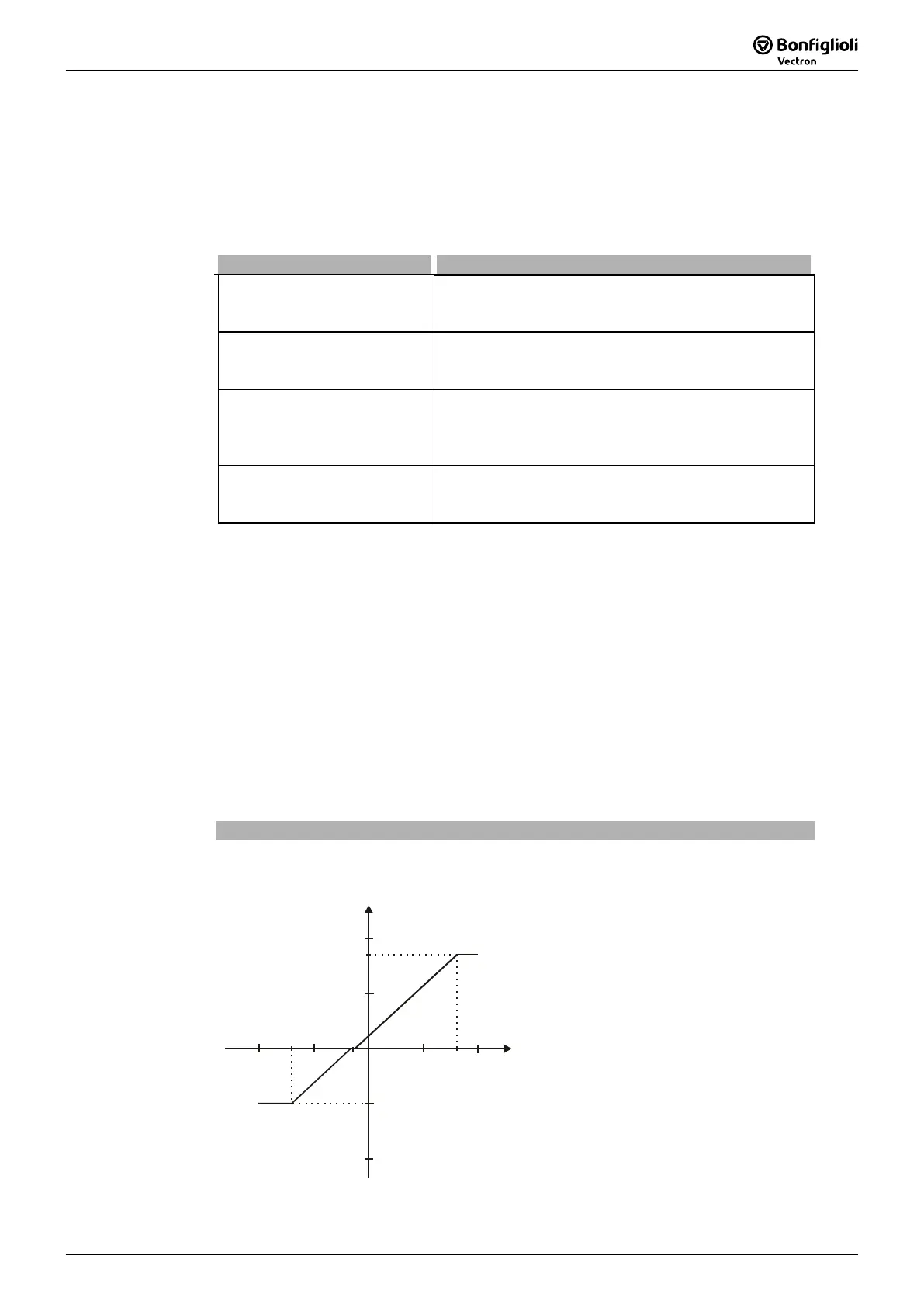
Operation mode "1 – bipolar"
In operation mode "1 – bipolar“, the characteristic of the analog input can be freely
set by stating two characteristic points.
Characteristic point 1:
X1 = -70.00% · 10 V = -7.00 V
Y1 = -50.00% · 50.00 Hz = -25.00 Hz
Characteristic point 2:
X2 = 80.00% · 10 V = 8.00 V
Y2 = 85.00% · 50.00 Hz = 42.50 Hz
Tolerance band:
ΔX = 2.00% · 10 V = 0.20 V
(X2=80% / Y2=85%)
8V
Y
X
-25Hz
42.50Hz
(X1=-70% / Y1=-50%)
-7V
The change of direction of rotation is done
in the example at an analo
input si
nal
of -1.44 V, with a tolerance band of ±0.20
V.

 Loading...