EM-RES-03 10/0714
5 System bus interface
The CAN connection of the system bus is physically designed according to ISO-DIS
11898 (CAN High Speed). The bus topology is the line structure.
The frequency inverter supports a CAN protocol controller, which may exist in either the
CM-CAN communication module with CANopen interface OR in an extension module for
the system bus, such as the EM-RES-03 extension module.
Attention: Installation of two optional components with CAN-Protocol controller
results in a deactivation of the system bus interface in the EM-RES-03
extension module.
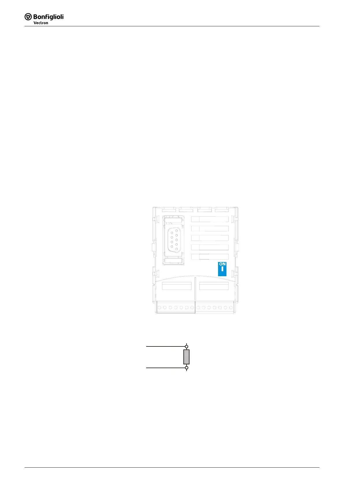
5.1 Bus termination
The necessary bus termination at the physically first and last node can be activated via
the DIP switch S1 on the EM-RES-03 expansion module.
− S1 built the normal passive termination.
•
Switch S1 to ON for a passive termination. This is necessary for the first and last
node.
S1
Attention: The factory setting for the bus termination is OFF (switch in
lower position).
CAN high (X410B.6
120
CAN low (X410B.5)
ata
ne
Data line
passive

 Loading...