EasyManua.ls Logo

bonitron M3645 - I;O Wiring

bonitron M3645
56 pages
Print Icon
To Next Page IconTo Next Page
To Previous Page IconTo Previous Page
Loading...
User’s Manual
23
3.4.2. I/O WIRING
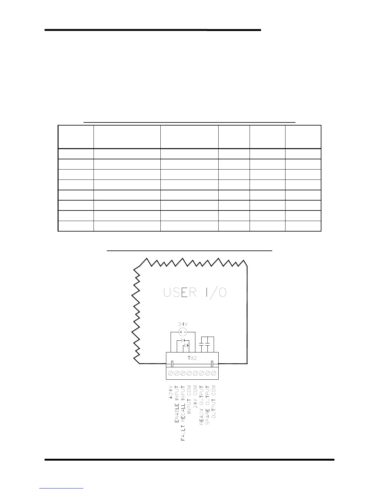
User I/O is connected via TB2 on the internal 3645C2 circuit board. To access
this terminal, the front panels of the unit must be temporarily removed. The
inputs can be driven either from an external 24VDC supply, or from the
internal 24V supply. To use the internal 24V supply, TB2-4 and TB2-5
must be shorted.
No additional I/O wiring is required for running multiple M3645 line regens in
parallel.
Table 3-6: M3645 30A, 50A, 100A User I/O Terminal Specifications
TERMINAL
FUNCTION
ELECTRICAL
SPECIFICATIONS
MIN WIRE
AWG
MAX WIRE
AWG
TORQUE
TB2-1
+24V
24VDC to TB2-5
18
16
2.2 lb-in
TB2-2
Enable Input
24VDC 5mA
18
16
2.2 lb-in
TB2-3
Fault Recall Input
24VDC 5mA
18
16
2.2 lb-in
TB2-4
Input COM
COM to TB2-2, -3
18
16
2.2 lb-in
TB2-5
24V COM
COM to TB2-1
18
16
2.2 lb-in
TB2-6
Ready Output NO
250V 150 mA
18
16
2.2 lb-in
TB2-7
Overtemp Output NO
250V 150 mA
18
16
2.2 lb-in
TB2-8
Output COM
COM to TB2-6, -7
18
16
2.2 lb-in
Note: Field wiring for terminals will be copper 75
°
C wire only.
Figure 3-6: M3645 30A, 50A, 100A User I/O Diagram
1 2 3 4 5 6 7 8

Table of Contents