User’s Manual
31
4. OPERATION
4.1. FUNCTIONAL DESCRIPTION
The M3645 line regen enables energy being generated by an over-hauling motor to
be efficiently returned to the power grid. Alternative solutions typically consist of
dissipating the returned energy in a resistor or simply allowing the motor to coast
uncontrolled to a stop.
The M3645 line regen synchronizes to the frequency of the attached power line,
automatically adapting to 50Hz or 60Hz. As the DC bus rises above the AC line peak,
the regen drives current from the DC bus into the AC line to limit the rise in bus voltage.
The regen is self-limiting, and will automatically fold back or shut down in the event
that unsafe conditions are detected. The internal structure of the regen prevents the
AC line from sourcing current to the DC bus.
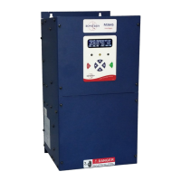
An optional digital display shows information about the regen's present status and
history. Fault records and a lifetime count of energy regenerated are stored. On units
without digital displays, system information is presented via three color LEDs.
4.2. FEATURES
4.2.1. DIGITAL DISPLAY
The optional display is a four-line, eighty-character LCD which shows
information about the present status of the regen, as well as records of faults
and energy throughput.
4.2.2. LEDS
Red, yellow, and green LEDs indicate the status of the regen.
4.2.2.1. POWER (GREEN) INDICATOR
The green LED indicates that the unit is powered on.
4.2.2.2. REGEN ACTIVE (YELLOW) INDICATOR
The yellow LED indicates that the unit is actively regenerating power back
to the line.
4.2.2.3. NOT READY (RED) INDICATOR
The red LED indicates that the unit is not ready to run. The red LED will
be off during normal operation.
On units with a digital display, the red LED will illuminate if a fault has
occurred, or if the unit’s enable input (4.5.2) is not activated. In case of a
fault, the display will indicate the nature of the fault.
On units without a digital display, the red LED turns on solid if the enable
input (4.5.2) is not activated. If any faults are present, the red Not Ready
LED will blink out a code indicating the present fault (Table 4-1).
4.2.3. BUTTONS
Up, down, left, right, cancel, and enter buttons are present on the face of
regen units equipped with a digital display. The function of each button
depends on the active screen. See Section 4.3 for details.