EN
15
Installation
www.bora.com
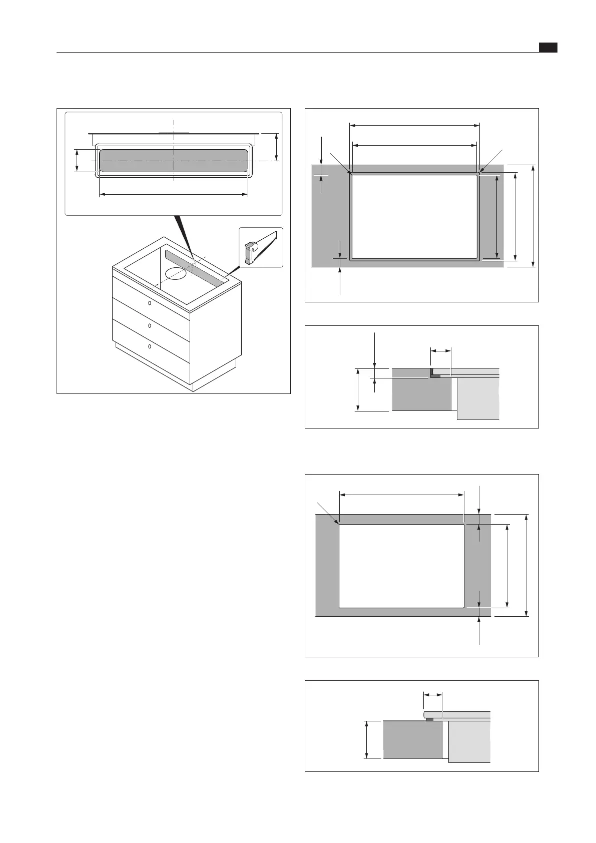
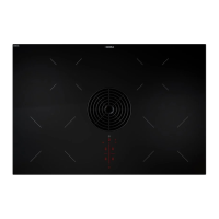
Cut-out dimensions for flush installation
764 ±2
735 ±2
519 ±2
≤ R5
≤ R5
≥ 50
(≥ 50)
490 ±2
≥ 600
Fig. 5.6 Cut-out dimensions for ush installation
6,5 +0,5
14,5
10 - 40
Fig. 5.7 Rebate dimensions for ush installation
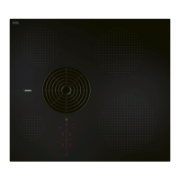
Cut-out dimensions for surface mounting
735 ±2
≤ R5
≥ 50
(≥ 50)
490 ±2
≥ 600
Fig. 5.8 Cut-out dimensions for surface mounting
12,5
10 - 40
Fig. 5.9 Overlay dimensions for surface mounting
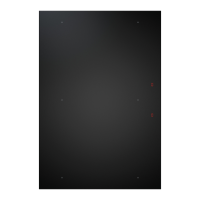
Creating a cut-out in the rear wall
90
650
118
Fig. 5.5 Rear wall cut-out
XX
Create the rear wall cut-out taking into account the specified
cut-out dimensions.
XX
A cable opening with a 14 mm diameter will need to be
provided either to the left or right of the rear wall cut-out.
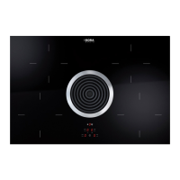
5.5 Creating the worktop cut-out
i
The minimum distance of 50 mm from the front edge of
the worktop to the worktop cut-out is a recommendation
from BORA.
XX
Comply with the instructions of the worktop manufacturer.
XX
Create the worktop cut-out taking into account the specified
cut-out dimensions.
XX
Make sure that the cut surfaces of the worktops are properly
sealed.