EN
18
Installation
www.bora.com
1
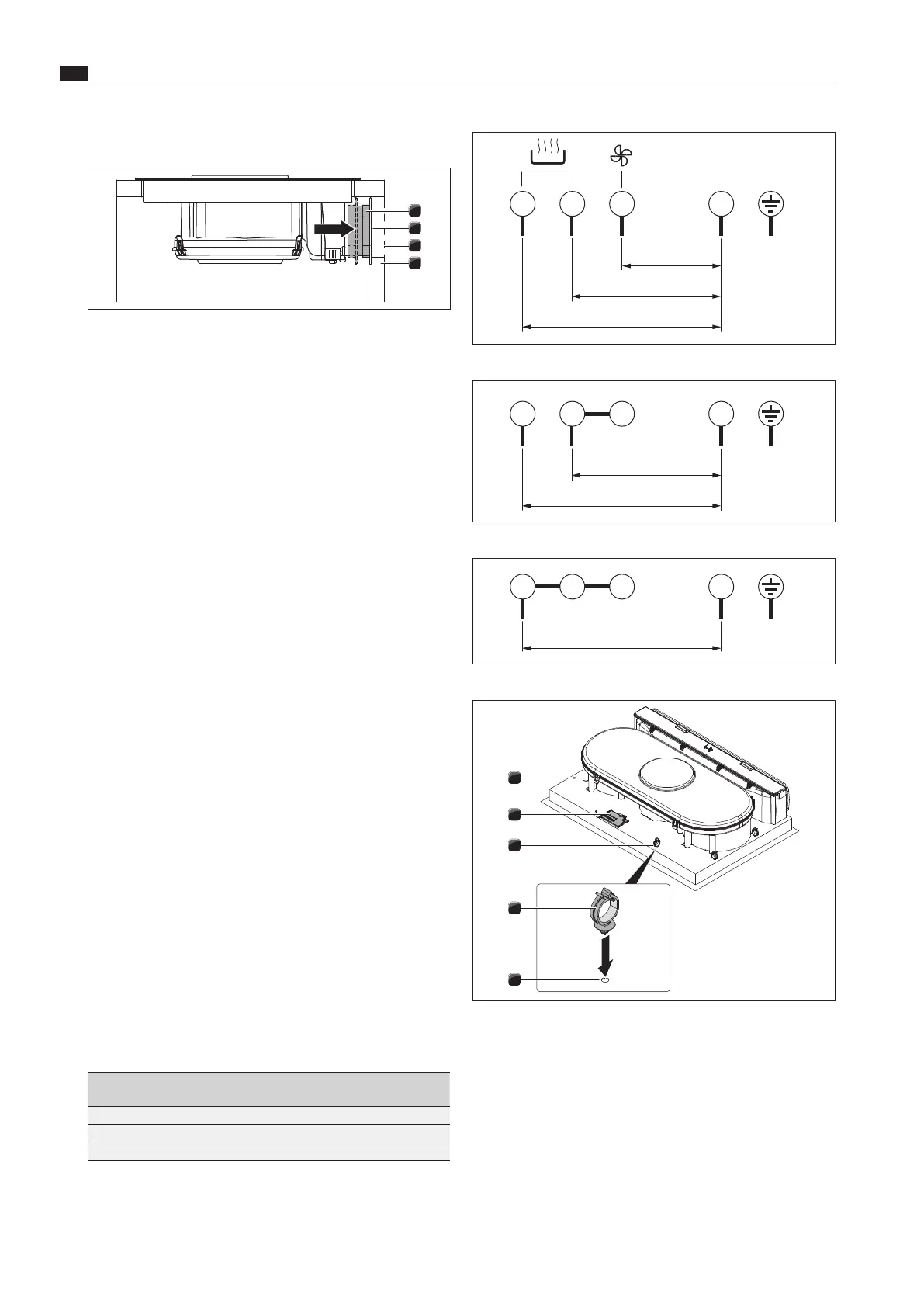
L1 L2 L3
2 3 4
N PE
220 - 240 V~
220 - 240 V~
220 - 240 V~
Fig. 5.20 Connection diagram 3-phase connection
1
L1 L2
2 3 4
N PE
220 - 240 V~
220 - 240 V~
Fig. 5.21 Connection diagram 2-phase connection
1
L1
2 3 4
N PE
220 - 240 V~
Fig. 5.22 Connection diagram 1-phase connection
3
3
1
1
2
Fig. 5.23 Electrical connections of the cooktop
[1] Bore holes
[2] Power supply
[3] Cable mounting clip
XX
Connect the power supply cable to the power supply [2] of the
cooktop with integrated cooktop extractor in accordance with
the relevant connection diagram (see fig. “Connection diagram”).
XX
For a one-phase or two-phase connection, connect the relevant
contacts using the BKAS connector clip (included in delivery).
Establishing a connection with the back wall
1
4
2
3
Fig. 5.19 Connection with the back wall
[1] Telescopic pull-out
[2] Adhesive tape
[3] Rear wall cut-out
[4] Back wall of unit
XX
Push the telescopic pull-out [1] until it is tight up against the
rear wall of the unit [4].
XO
With the telescopic pull-out the distance to the rear wall cut-
out [3] can be flexibly bridged.
XX
Check that the telescopic pull-out [1] is flush with the rear wall
of the unit [4] and closes it off.
XX
Ensure that the telescopic pull-out [1] is firmly attached to the
rear wall of the unit [4].
5.7 Establishing the power
connection
XX
Observe all safety and warning information (see the “Safety”
chapter).
XX
Observe all national and regional laws and regulations as
well as the supplementary regulations of the local utility
companies.
i
The power connection may only be established by certified
specialists. The specialist also assumes responsibility for
the proper installation and commissioning.
i
Connections via plug-in contacts (Schuko plugs) are not
permitted.
XX
Switch off the main switch/automatic circuit breaker before
connecting the cooktop.
XX
Secure the main switch/automatic circuit breaker against
being switched back on without permission.
XX
Make sure the power to the appliance is disconnected.
XX
Connect the cooktop exclusively via a fixed connection to an
H 05 VV-F power supply cable with corresponding minimum
cross-section (see Table “Fuse protection and minimum
cross-section”).
Connection Fuse protection Minimum cross-
section
3-phase connection 3 x 16 A 2.5 mm
2
2-phase connection 2 x 16 A 2.5 mm
2
1-phase connection 1 x 32 A 4 mm
2
Tab. 5.2 Fuse protection and minimum cross-section