4.4.4 Aligning the unit
After the Börger machine is installed, in order to rule out damage
caused by displacement, you must check the alignment of the cou-
pling on units mounted on a base frame that have gear motors.
NOTE!
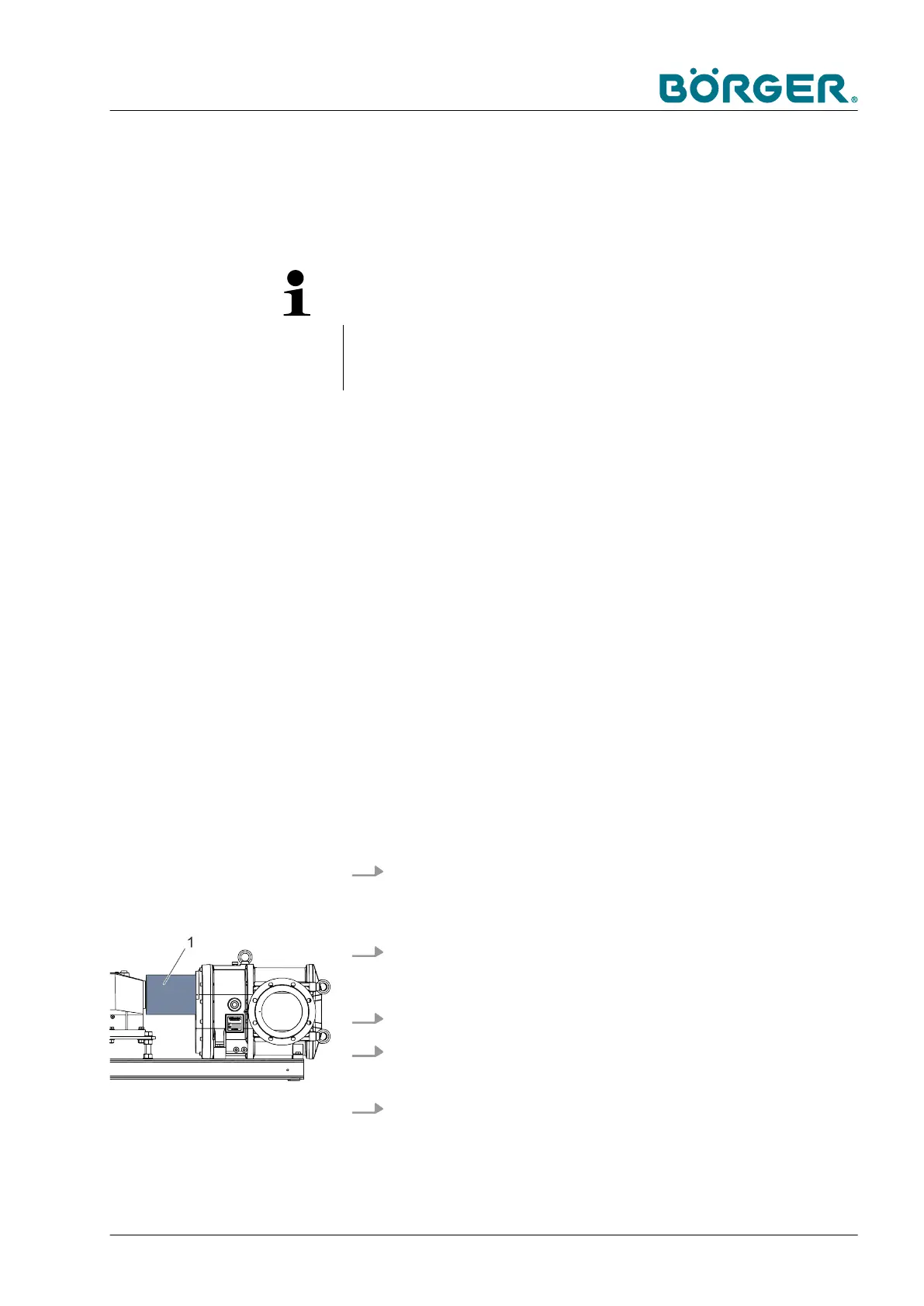
Coupling guard
— The coupling guard is a safety-relevant protection component.
It prevents personnel from reaching into rotating parts.
Personnel:
n
Mechanics
Protective equipment:
n
Occupational safety clothing, chemical
resistant
n
Safety shoes
n
Safety gloves, chemical-resistant
n
Safety goggles
Special tool:
n
T
ools, general
— Read and follow the safety instructions detailed in
Ä
Chapter
2.12 “Safety instructions for maintenance and rectifying mal-
functions” on page 30.
— Read and observe the instructions from the coupling manufac-
turer in the appendix.
— To the extent necessary, amply secure the surrounding area
when performing installation. Cordon off the working area with
a red and white safety chain and a warning sign.
1. Loosen the fastening screws of the coupling guard and pull
the coupling guard out of the groove of the fastening ring, if
available (depending on version).
2. Bend up the coupling guard (1) shown here slightly
.
3. Lift of
f the coupling guard (1).
4. Check the alignment of the coupling in several positions
using a suitable tool (straightedge, laser-optical sensor).
5. When necessary
, carefully correct any misalignment
according to the specifications of the coupling manufacturer,
e.g. using the set screws on the motor plate.
Version with torsionally
flexible coupling
Transportation, Storage and Installation
BA-Classic FL_en-US, 03.05.2018 www.boerger.de / www.boerger.com 71