Монтаж и пуск INGENIO COMPACT ИБП 10÷20 кВА
Installation and start-up of INGENIO COMPACT 10÷20 kVA
64 OMS90050 РЕД. / REV. A
4.5 INTERFACES AND EXTERNAL CONNECTIONS
The UPS is provided with serial interfaces and external connection facilities for the
communication of the operating status and parameters.
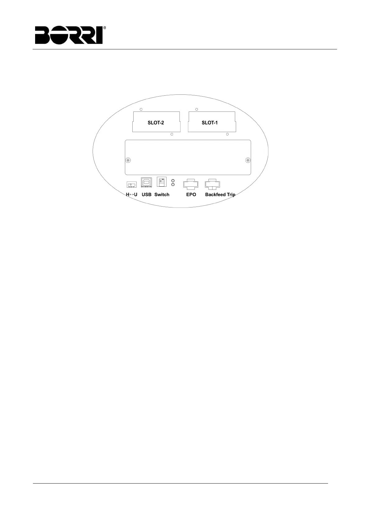
Picture 8 – Position of the interfaces of INGENIO COMPACT 10÷20 kVA
PARAL-1 & PARAL-2: parallel communication ports (optional)
SWITCH: used to insert a termination resistor in the parallel communication line
HMI: communication port for control panel, this port connects to the LCD display and
control panel.
H↔U: used to select HMI or USB port. Ensure this switch is on “H” position to have the
HMI port operational.
USB: service only.
LED Status Indicators
Normal: correct operation
Alarm: the UPS has some abnormal conditions
EPO (Emergency Power Off): this contact allows to turn off the UPS in an emergency.
Closing the contact will turn the UPS off immediately.
Back-feed Trip: back-feed protection contact.
Communication Slot1: this slot can house the relay card or RS-485 MODBUS card.
Communication Slot2: this slot can house the relay card or SNMP card. Ensure the SW2
switch is set to the correct position when this slot is used.