Bosch Sensortec"| BST-BMP581-DS004-02 27 | 74
Modifications reserved | Data subject to change
without notice Document number: BST-BMP581-DS004-02
POR interrupts are not supported with I3C IBI, as the device is not in a state where I3C is initialized after power-up
reset. Also, the interrupt pin will not flag an POR interrupt, as the interrupt pin is disabled after power-up.
The status of the interrupt can be read from INT_STATUS.por. A read of the INT_STATUS will clear the status.
4.7.3 Interrupt pin
The BMP581 provides an interrupt pin (INT), which allows to signal certain events to the host processor.
4.7.3.1 Interrupt pin configuration
The behavior of the interrupt pin can be configured in INT_CONFIG with these fields:
int_mode: The interrupt mode can be „pulsed“ or „latched“. Latching determines when an interrupt is released (see
Chapter 3.7.3.2 for details)
int_pol: The interrupt polarity can be configured to be either „active high“ or „active low“
int_od: The interrupt pin can be configured to be „open-drain“ or push-pull“
int_en: The interrupt pin can be enabled. With enabled interrupt pin, all interrupt sources configured in INT_-
SOURCE will be ORed on the interrupt pin.
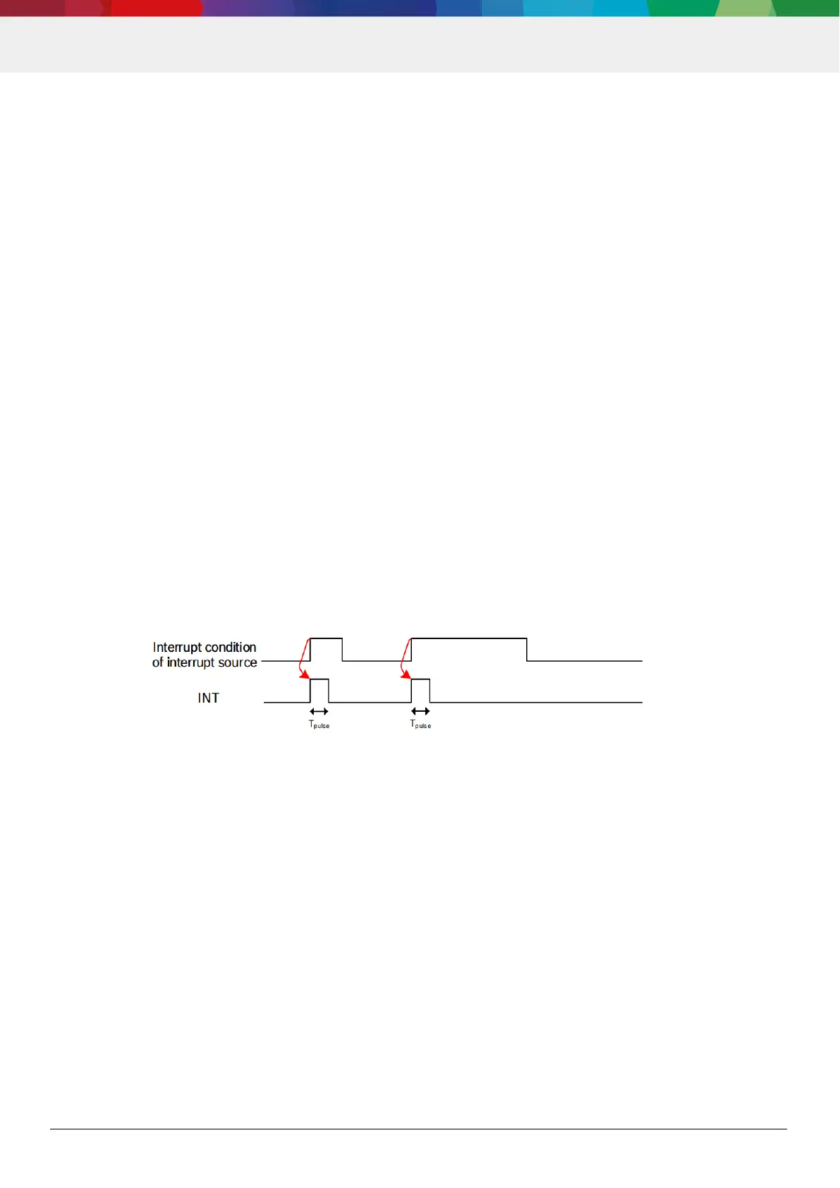
4.7.3.2 Interrupt Timings
Interrupt timings depend strongly on the int_mode setting:
Pulsed mode. In the pulsed mode the INT pin creates a pulse on the interrupt pin, each time an interrupt condition
changes from FALSE to TRUE, and the interrupt source is enabled in INT_SOURCE. Figure 5 shows the timing of
pulsed mode.
The pulse length is t
int_pulse
. Between two pulses, there is a minimum gap of t
int_deassert
in which the pin will stay de-
asserted.
Figure 5: INT pin timing in pulsed mode