SystemModules
FlexibleAutomation
4−20
4.2.3 Settings
V.24/20 mA Interface The serial data signal is transferred to the 25−pin D connector as V.24
and 20 mA signals.
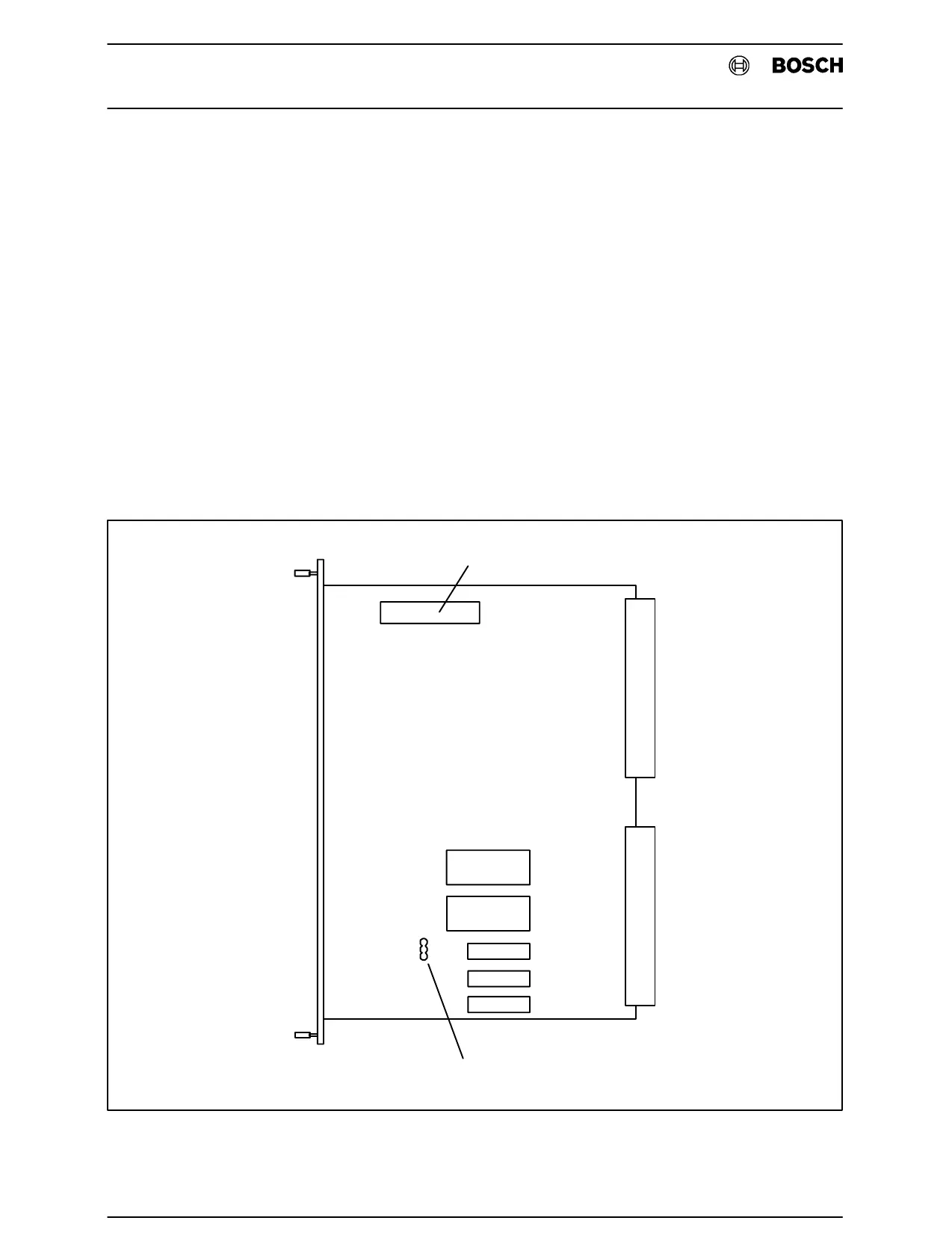
With the JP2 (see Fig.4−6) jumper in position A, data transfer is made
without a control signal.
With the JP2 (see Fig.4−6) jumper in position B, data transfer is made
with a control signal.
The ZE is supplied with the basic setting in position "B".
A
B
JP2
S1
Fig.4−6ZE300/301 Settings