SystemModules
FlexibleAutomation
4−28
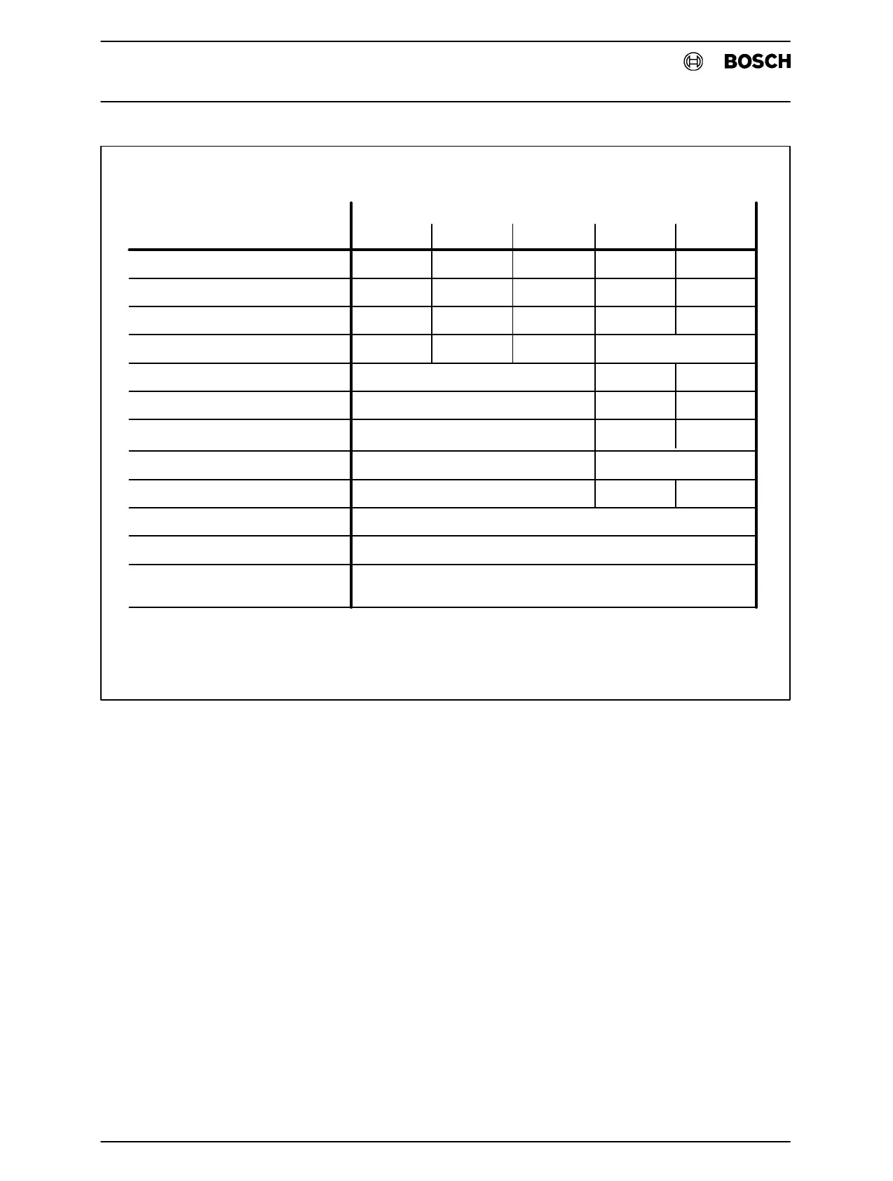
DigitalInputModules
InputVoltage
NumberofInputs
2−pin
FrequencyRange
Logic"0"VoltageRange
Logic"1"VoltageRange
InputCurrent
SwitchingDelay"ON"
SwitchingDelay"OFF"
SimultaneityFactor
Width
InternalPowerConsumption
4.3.1.1 4.3.1.2 4.3.1.3 4.3.1.4 4.3.1.5
24VDC 24VDC 24VDC 230VAC 115VAC
32 16 16 16 16
no no yes yes yes
−− −
47−63Hz
−3V...+6V 0−65V 0−35V
+15V...+30V 175−255V 88−133V
approx.15mA
approx. approx.
approx.3ms 5mstypical
approx.3ms 25mstyp. 30mstyp.
100%
1modulewidth
approx.0.5mAperactivatedinput
(12V)
5.5mA 6mA
seeparagraph
Fig.4−8Specifications of input modules
Connection All transducers are connected by plug−in terminals. This allows module
replacement without removal of the wire connections.
Cable Cross−section: 1.5mm@ max.
Current Capacity of 1 Terminal: 6A max.
.Note,
The input modules require the 0V connection. No external voltages other than the signal voltage are
required.