41
1
3
X4
F3 F2 F1
V21
V19
V23
V22
V26V27V24
458797-13
1
2
3
424V_E
12V_E
P1
4
WH (ws)
BN (bn)
GN (gn)
X4
X5
X6
T2
V1
F6
202 1
19
BK
RD
RD
0V
12V
24V
V2
F7
222 1
21
A10
EPS
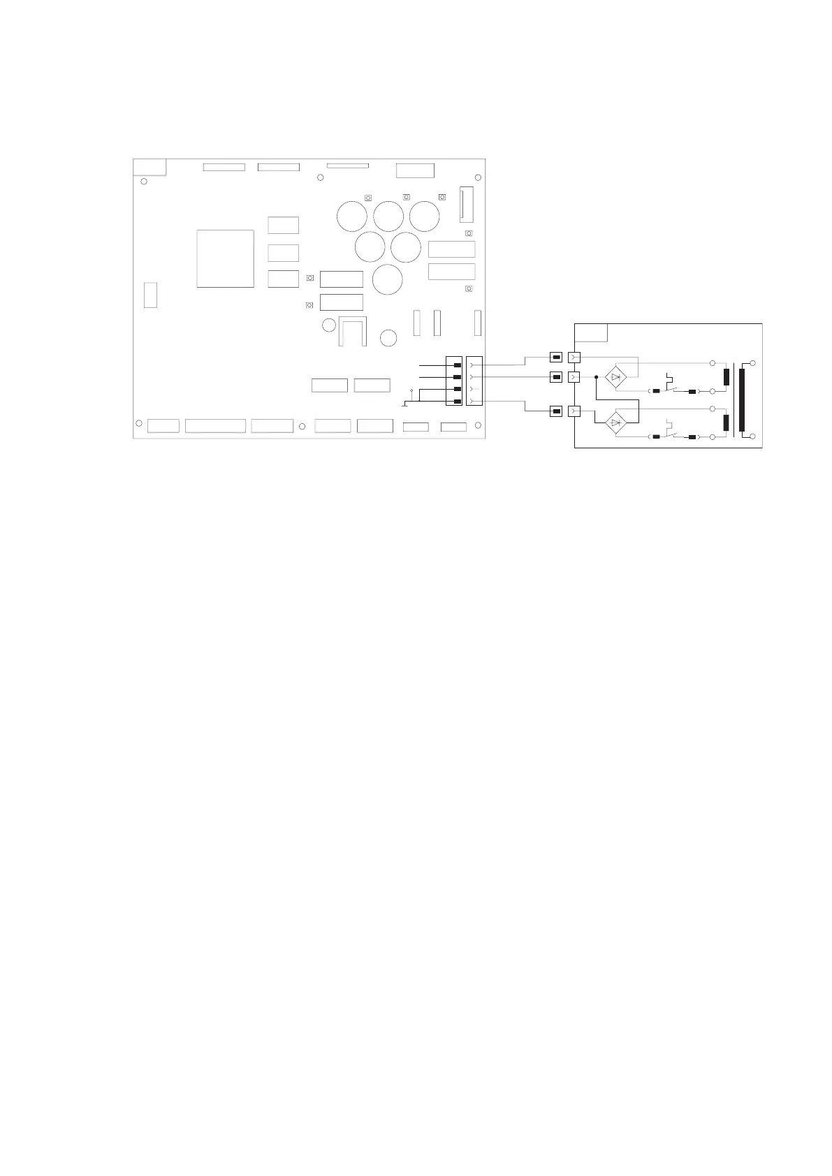
4.1.1 Check 12 V / 24 V power supply
Circuit diagram:
The control device supply voltage is provided by way of
external terminals (X4-X6) on the EPS switch cabinet.
! Never disconnect or connect the control device’s po-
wer supply when the test bench is switched on. This
could destroy the control PCB.
Before disconnecting / connecting the power supply,
switch off the test bench at the main switch.
Procedure:
1. Check correctness of power supply cable (X4).
2. Check output voltages (12V and 24V) at external ter
-
minals (X4-X6) on EPS switch cabinet.
If no voltage applied:
– Activate circuit breaker (F6/F7).
– Check internal power supply of EPS according to
EPS repair instructions 1 689 975 140.
3. Check fusible cutouts F1, F2 and F3 on control PCB.
4.
Check continuity of power supply cable 1 684 465 485
(X4).
5. Check continuity of connecting cable 1 684 465 484
(X7) to the rail PCVs.
6. Perform electrical test on rail PCVs (see Chapter
4.3.1).
7. Replace control PCB (A10.1).
 Loading...