49
9. Close anti-splash guards.
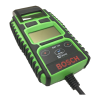
10. Use feeler gauge or gauge block (x=1.5mm) to set di
-
stance between contact screw and proximity switch.
11. Tighten proximity switch and check distance again.
12. Pull connecting cable through the cable screw connec
-
tion on the terminal box.
i For the B13 proximity switch connect the connecting
cable to the X10.2 plug on the terminal box.
13. Connect connecting cable (for B11 and B12 only) in
terminal box.
14. Tighten cable screw connection.
15. Close terminal box.
5.3 Replacing high-pressure rail
Procedure:
1. Switch off EPS on main switch.
2. Detach high-pressure and return hoses.
3. Detach connecting cables to rail PCVs.
4. Undo fastening screws and remove connector from
pressure sensor.
5. Remove fastening screws on underside.
6. Remove high-pressure rail from retaining bracket.
7. Mount new high-pressure rail onto retaining bracket.
8. Detach connector from pressure sensor.
9. Mount individual components in reverse dismantling
order.
i It is not necessary to follow a specific sequence when
fitting the connectors to the PCVs.
! When fitting, makes sure that all plugs latch properly
into place.
5.4 Replacing pressure limiting valve
Procedure:
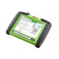
1. Switch off EPS on main switch.
2. Unscrew pressure limiting valve (1).
Series ) FD 684
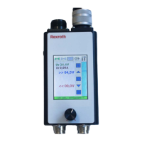
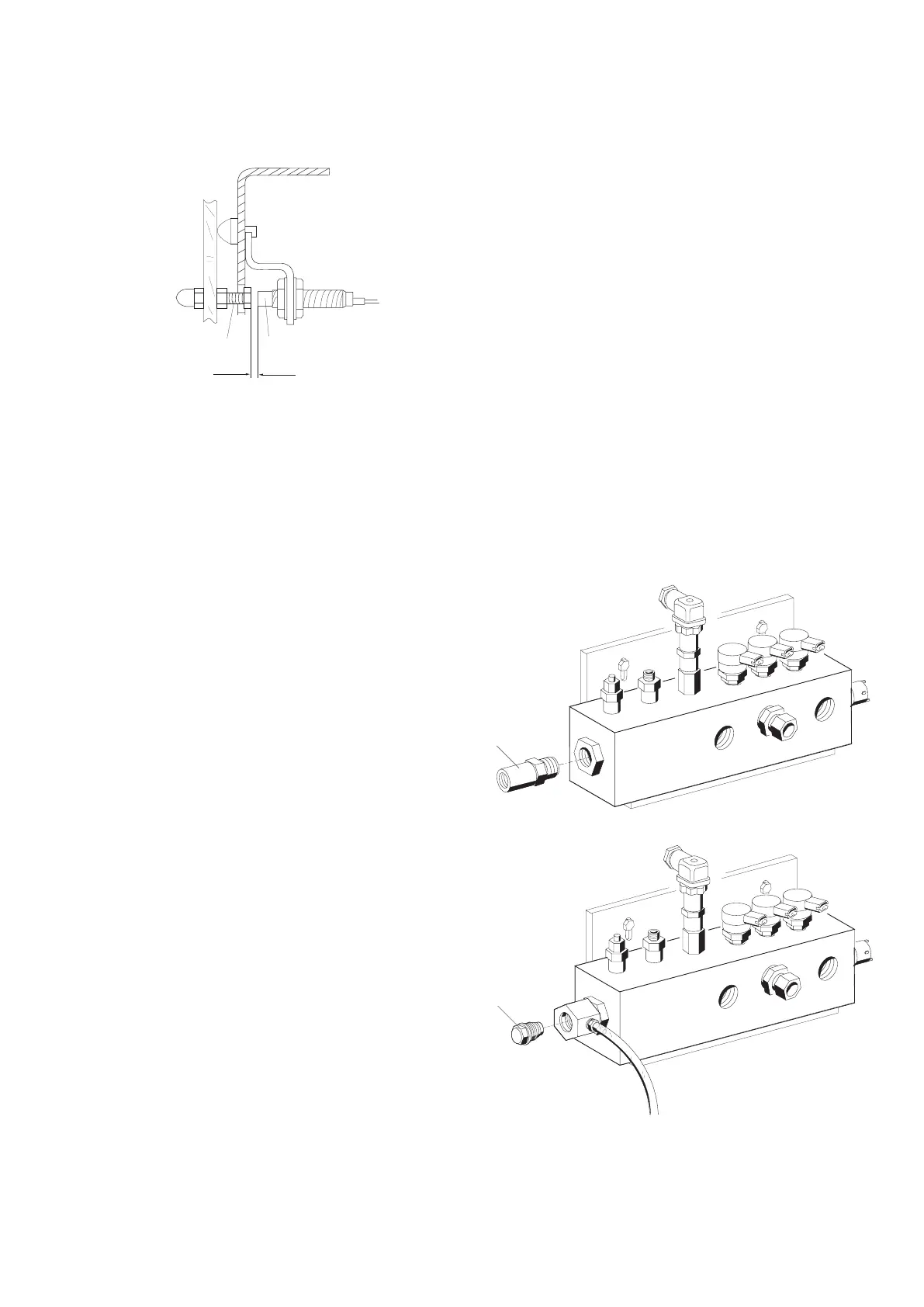
Series ( FD 684
3. Lightly oil thread of new pressure limiting valve before
assembly.
4. Screw in pressure limiting valve and tighten to 70 Nm.
5. Turn pressure limiting valve back through 90° and
tighten again to 100 Nm.
 Loading...