48
5. Repair
! When tightening screws with a cutting edge the fol-
lowing procedure must be observed:
1. Lightly oil threaded screw.
2. Tighten screwed connection to 70 Nm.
3. Turn screwed connection back through 90°.
4. Tighten screwed connection to 100 Nm.
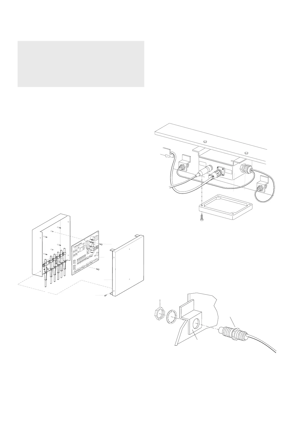
5.1 Replacing A10 control printed circuit board
Procedure:
1. Switch off EPS on main switch.
2. Remove fastening screws (1).
3. Remove housing cover (2).
4. Detach all connecting cables from printed circuit
board.
5. Remove both fastening screws (3).
6. Detach printed circuit board (4) from spacer clips.
7. Plug in new printed circuit board to spacer clip.
i The spacer clips lose their clamping effect when PCBs
are frequently plugged in. In such a case use a screwdri-
ver to slightly force the spacer clips apart when the PCB
is plugged in.
8. Mount individual components in reverse dismantling
order.
5.2 Replacing inductive proximity switch
Procedure:
1. Switch off EPS on main switch.
2. Open anti-splash guards.
3. Open terminal box (1) and disconnect electrical cable
for proximity switch (for B11 and B12 only).
i For the B13 proximity switch (at front-end door) only
the X10.2 plug connector of the terminal box need be
removed.
4. Undo cable screw connection (2) on terminal box.
5. Withdraw connecting cable from terminal box.
6. Use 17mm open end wrench to undo front hexagon
nut (3) and remove it.
7. Remove proximity switch (4) from retaining bracket
(5).
8. Mount new proximity switch to retaining bracket using
hexagon nut and toothed disk.
i Do not tighten hexagon nut.
 Loading...