45
4.2.1 Check safety monitoring
Procedure:
1. Switch on EPS on main switch.
2. Close all anti-splash guards.
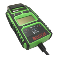
3. Check LEDs (1) on rear of proximity switch (B11-
B13).
LED on Switching contact given OK
LED off Switching contact missing NOK
4. Check status of LEDs V19 and V20 (see also Chapter
5.1) on control PCB (A10).
If faulty:
1. Check air gap X between proximity switch and contact
screw (see Chapter 5.2).
If air gap not OK: Adjust air gap
Air gap X 1.5 mm
2. Check 12V power supply at X14 connector on control
PCB (A10).
Pin 4 12V
Pin 5
If 12V power supply not OK:
Check power supply of control PCB (see Chapter
5.1).
or
check continuity of connecting cable 1 687 465 486
(X14).
3. Check signal voltage (approx.11.8V) at X14 connector
on control PCB (A10).
B11 B12 B13
Pin1 Pin2 Pin3 Pin5
If signal voltage not OK:
Check continuity of connecting cable 1 687 465 486
(X14).
or
check wiring in terminal box (X10).
or
replace proximity switch.
4. Check wiring in terminal box (X10).
5. Replace proximity switch.
4.2 Safety monitoring
While testing common-rail high-pressure pumps test
pressures of up to 160 MPa (1600 bar) may be generated
in the test system. In order to protect the operator, an
anti-splash guard with inductive proximity switch safety
monitoring is a necessity.
The anti-splash housing consists of a frame with three
large wing doors. The entire housing is mounted on the
oil collector of the EPS.
The inductive proximity switch and attendant terminal
box are located at the top of the frame in the anti-splash
housing. If the safety monitoring is triggered through the
wing doors being opened, the control device de-energizes
the pressure control valves in the rail. This in turn causes
the test pressure to drop to less than 20 MPa (200bar).
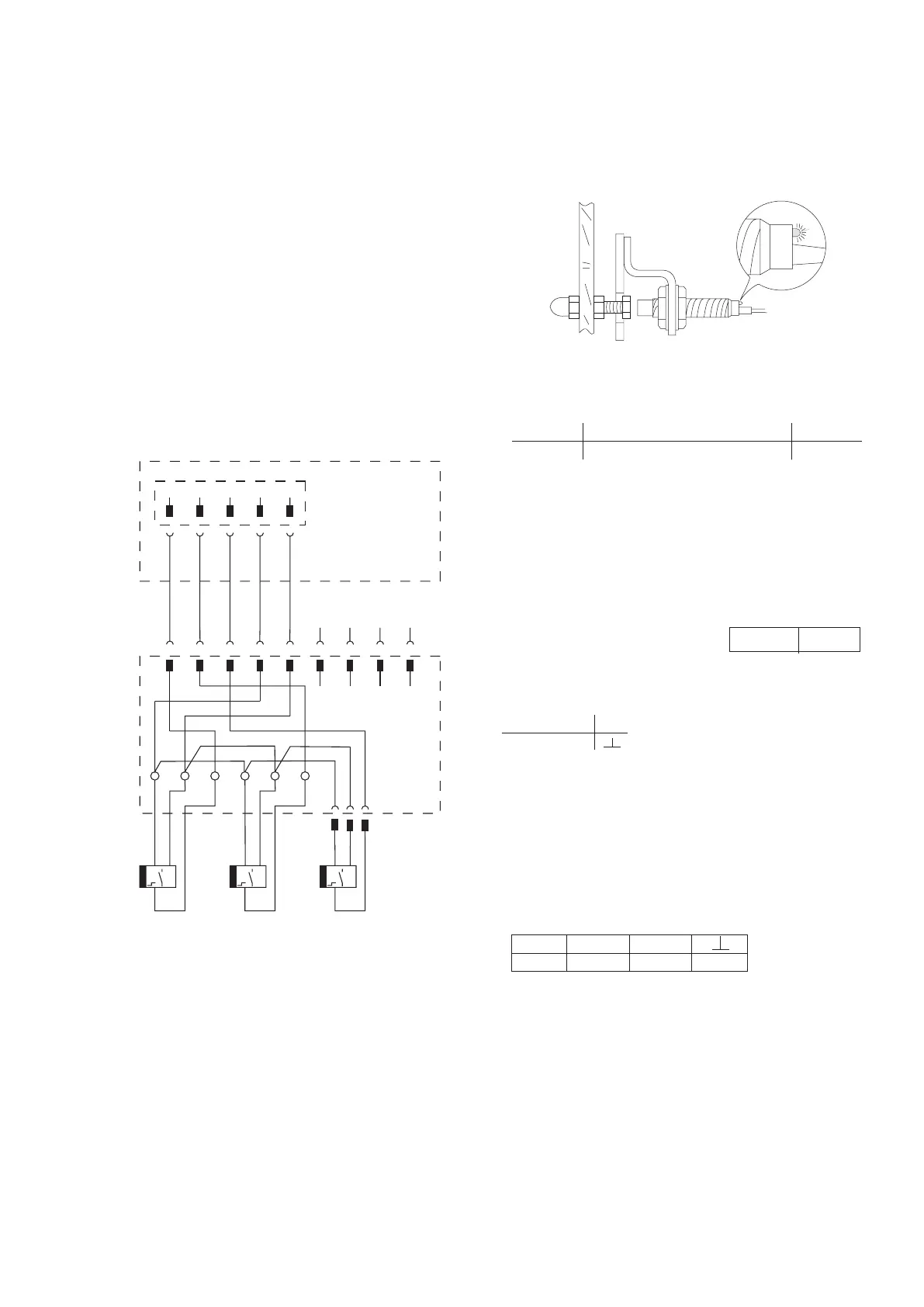
Circuit diagram:
+ -
X14
A10
X10
B11
+ -
B12
B13
1
1
1
1
1
2
2
2
2
2
3
3
3
3
3
4
4
4
4
5
1
2
3 4
5
5
5
6
6
8
8
7
7
6
5
WH (ws)
BN (bn)
BN (bn)
BN (bn)
BN (bn)
BU (bl)
BU (bl)
BU (bl)
BK (sw)
BK (sw)
BK (sw)
GN (gn)
YE (ge)
GY (gr)
9
9
+ -