4.2 Filling with oil
4.2 Rernplissage d'huile
After the test bench has been connected to the electricity
(and,
if necessary, water) supply, the Boehringer-Sturm
hydraulic transmission must be filled with oil. The
oil
reservoir for the hydraulic transmission can be reached after
removal of the side panel. Unscrew and raise
lid of oil reser-
voir and pour one of the oils specified in section
7.5
into the
reservoir
i~ntil the valves are covered. The oil level should be
checked after the
oil transmission has been ventilated (see
section
7.4.).
The intermediate gear transmission will already have
been filled with transmission
oil (BOSCH
01
1
V
1
).
The oil
level must be visible in the filler opening (below plate in fig.
7).
The test-oil reservoir must be filled with approx.
50
Itr. of
test
oil01
61 vll*.
The test oil is poured directly into the test-
oil reservoir after unscrewing the left-hand half of the lid.
The
oil in the reservoir should not sink below the level of the
sight glass and should be replenished when necessary.
Do not operate the test bench before filling with oil.
*
If the BOSCH oil
01
61
V
11
cannot be obtained outside
Germany,
))Shell Calibration Fluid B<< can be used (not
obtainable in Germany).
4.3 Test-oil cooling
The test benches are basically designed to operate with the
internationally accepted test-oil temperature of
400
C
rt5
(104
F
f
9).
For carrying out tests at test oil temperatures
lower than
350
C
(95O
F), special test bench versions with a
built in thermostatically or
manually controlled water cooling
system for the test oil can be supplied on request.
The EFEP
390
test bench is fitted with a thermostatically
controlled water-cooling
system as standard equipment.
The cooling-water inlet und outlet connections emerge at
the bottom of the front panel and have a
112"
withworth
pipe thread. An arrow serves to identify the water inlet.
About
1000
Itr. of cooling water are needed every working
day for a temperature difference of
about
25O
C
(450
F) be-
tween water and test
oil. Naturally, this figure for the cooling
water requirement can serve only as a guide, as the actual
requirement will be affected by many factors,
e.g., ambient
and cooling water temperature, the size of pumps being
tested, etc.
The thermostatically controlled water-cooling systems
Comes into operation when the test-oil temperature rises
above
400
C
(1
04O
F).
If the thermostat valve has to be adjusted, a greater cooling
effect is achieved by turning its
Setting disc in the direction
of the arrow (fig.
5).
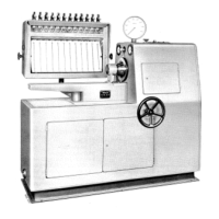
Fig.
5
Test bench EFEP
390
with lower hinged doors Open
1
Electrical switchbox
2
Test-oil reservoir
3
Thermostat valve (water-cooled model only)
4
Overflow valve (3 kgf/cm2
=
42
psi)
5
Non-return valve
6
Throttle 4 for vacuum
7
Throttle
3
for heating
Apres le branchement electrique (et eventuellement raccord
A
une
conduite d'eau), remplir
la transmission hydraulique Boehringer-
Sturm d'huile. Le reservoir
A
huile est accessible apres enlevement
de la paroi frontale. Devisser le couvercle du reservoir et remplir ce
dernier avec I'une des huiles
indiquees au paragraphe
7.5
jusqu'au
recouvrement des soupapes.
Apres purge d'air de la transmission
hydraulique,
verifier le niveau d'huile (paragraphe
7.4).
L'engrenage intermediaire est d6jA rempli d'huile pour boites de vi-
tesses (BOSCH
01
1
v
1
).
Le niveau de I'huile doit etre visible par
I'ouverture de remplissage
(voir fig.
7).
Le reservoir
A
huile d'essai doit etre rempli avec
50
1
environ d'huile
d'essai doit
etre rempli avec
50
1
environ d'huile d'essai
Le reservoir
A
huile d'essai doit etre rempli avec
50
1
environ d'huile
d'essai
01
61
V
II*,
que I'on y Verse directement apres avoir retire le
demi-couvercle gauche.
Le niveau d'huile ne doit pas descendre en dessous du voyant de
controle de niveau. Le cas echeant rajouter de I'huile.
Ne pas mettre
le banc d'essai en service avant le remplissage
d'huile.
*
Si, dand les pays autres que I'Allemagne, on ne peut passe pro-
curer d'huile BOSCH
01
61
V
11,
on peut utiliser
a
la place I'huile
"Shell Calibration Fluid
B"
(ne peut etre en Allemagne).
4.3 Refroidissement de I'huile d'essai
Le banc d'essai est concu pour fonctionner avec Une huile
A
la
temperature de
40
f
5O
C (valeur internationale). Pour les essais
aux
temperatures inferieures
A
35O
C sont livres sur demande des
equipements
speciaux pour refroidissement de I'huile d'essai avec
commande manuelle ou thermostatique.
Le banc d'essai EFEP
390
est 6quipb en serie d'un dispositif de re-
froidissement de I'huile d'essai avec commande thermostatique.
Les raccords
d'arrivee et de depart de I'eau de refroidissement
apparaissent en dessous du couvercle de
la paroi frontale. Ils ont
un filetage
112".
Une fleche indique le raccord d'arrivee.
Pour Une difference de ternperature de
25O
C entre I'arrivee d'eau
et l'huile d'essai,
la consommation en eau est d'environ
.I000
litres
par jour. Ceci n'est donne qu'A titre indicatif. La consommation
reelle est fonction de nombreuses
donnees, par exemple
temperature de I'eau, ternperature ambiante,
taille de la pompen
en essai, etc.
.
\
Le refroidissement par eau avec regulation thermostatique com-
mence
A
fonctionner lorsque la ternperature de I'huile depasse
40'
C.
S'il est necessaire de corriger le reglage de la soupape thermosta-
tique, Une rotation du disque de reglage dans le Sens de la fleche
entraine un plus grand debit de I'eau de refroidissement (fig.
5).
Figure
5
Banc EFEP
390
les portes du bas etant ouvertes
1
Boite de distribution
2
Reservoir d'huile d'essai
3
Soupape thermostatique
4
Soupape de decharge 3 kgf/cm2
5
Clapet de non-retour
6
Etranglement
4
pour depression
7
Etranglement
3
pour echauffement