14 en | Technical Specifications Aspirating Smoke Detector
2018.04 | 2.0 | F.01U.130.926 Operation Guide Bosch Sicherheitssysteme GmbH
To set the FCS-320 to the airflow typical for the pipe network, an airflow initialization (flow-
init) procedure is carried out. This must be done for each unit once at the start after
installation, each time the pipe system is replanned/redesigned and after changing the fan
voltage. This enables the unit to determine and save the airflow typical for the pipe network.
Pipe System
A pipe system with an overall length of up to 300m can be connected to FCS-320 series
aspirating smoke detectors over a maximum of 32 aspiration points. Two pipe systems can be
connected to both the FCS-320‑TP2 and FCS-320‑TT2 variants. The entire pipe system then
has a total length of 2 x 280m and a maximum number of 2 x 32 aspiration points.
3.5 FCS-320 Series Aspirating Smoke Detectors and Accessories
3.5.1 Overview
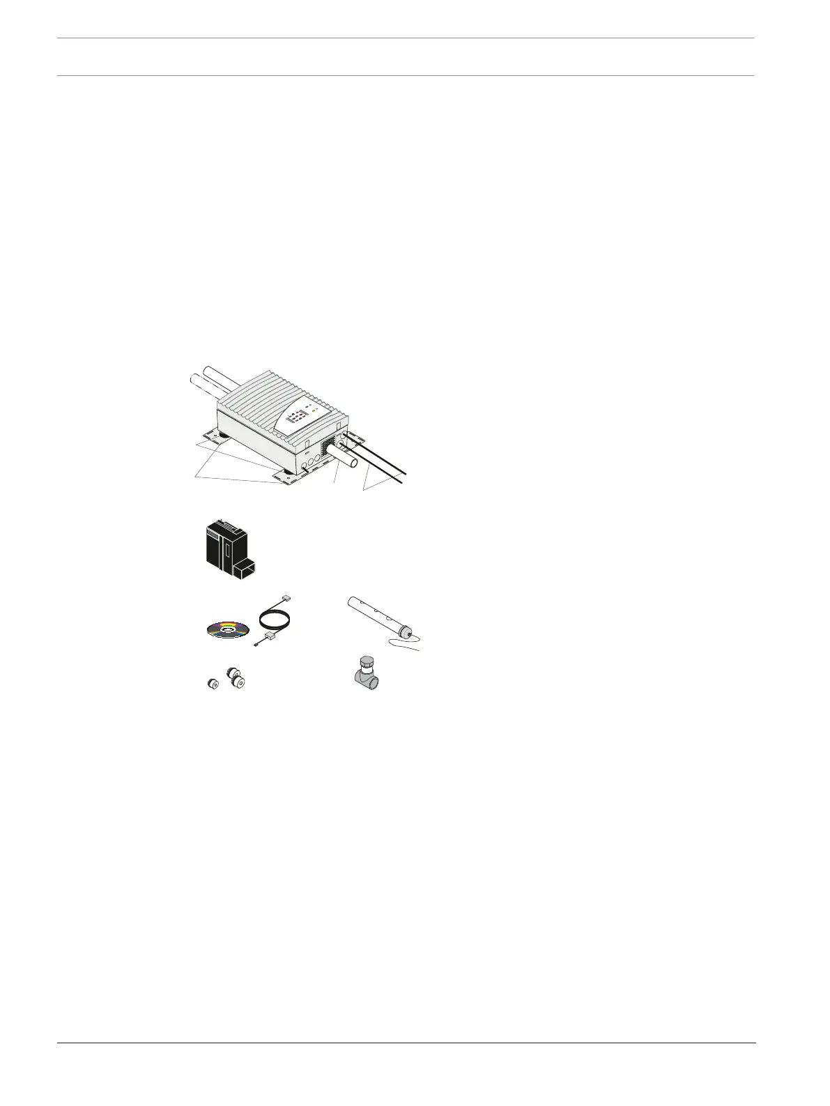
Overview of FCS-320 series aspirating
smoke detectors and accessories
1 Pipe system(s)
2 Connections to fire panel/power supply
3 Air-return pipe
A Vibration absorber (sold separately)
B MT-1 unit mounting
C Detector module
D DIAG Diagnostic Software with connection
cable
E Cable bushings (1xM20, 2xM25)
F Test pipe
G Test adapter
FCS-320 series aspirating smoke detectors comprise the following components:
– Plastic housing
– Plastic connection pieces
– Integrated air-return pipe
– Connection for pipe with 25mm external diameter
– Aspiration unit with optimized air supply
– Motherboard with interface for diagnostics system, LSN connections, connection for
shield wire, as well as DIP switch for address setting
– Supplementary package with cable bushings (1xM20, 2xM25)
– FCS-320-TP1 /FCS-320-TP2: optical displays for alarm, malfunction and operation
– FCS-320-TT1 /FCS-320-TT2: smoke level display(s), optical displays for info, pre and main
alarm, malfunction and operation
– 1 detector module (for FCS-320-TP1 and FCS-320-TT1) and/or 2 detector modules (for
FCS-320-TP2 and FCS-320-TT2).