Aspirating Smoke Detector Installing the Aspirating Smoke Detector | en 87
Bosch Sicherheitssysteme GmbH Operation Guide 2018.04 | 2.0 | F.01U.130.926
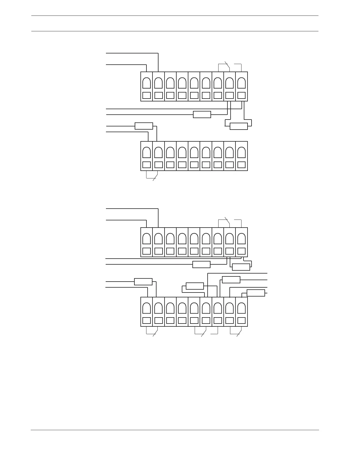
5.6.2 FCS-320-TP1 / FCS-320-TT1 Connection to the Fire Panel
9 8 7 6 5 4 3 2 1
9 8 7 6 5 4 3 2 1
X7
X6
+
-
AL1
Stö 1
L1
+
-
24V
R
A
R
E
+
-
L2
R
E
5.6.3 FCS-320-TP2 / FCS-320-TT2 Connection to the Fire Panel
9 8 7 6 5 4 3 2 1
9 8 7 6 5 4 3 2 1
X7
X6
AL1
Stö 1
+
-
24V
Stö 2
AL2
-
+
L3
R
A
+
-
L1
R
A
R
E
+
-
L2
R
E
-
+
L4
R
E
R
E
5.7 DIP switch settings
The aspirating smoke detector parameters are set using the DIP switch on the detector
modules. The default settings are marked in bold in each case. Select all other parameters
(see tables).