86 en | Installing the Aspirating Smoke Detector Aspirating Smoke Detector
2018.04 | 2.0 | F.01U.130.926 Operation Guide Bosch Sicherheitssysteme GmbH
1. Punch out the cable entries using a sharp object.
Caution: Do not cut the cable entries with a knife!
– Route the connection cable(s) (max. 2.5mm2) through the prepared M20 or M25
connections and into the unit. Now cut these to the required length inside the unit.
– Wire the unit according to the connection information described below.
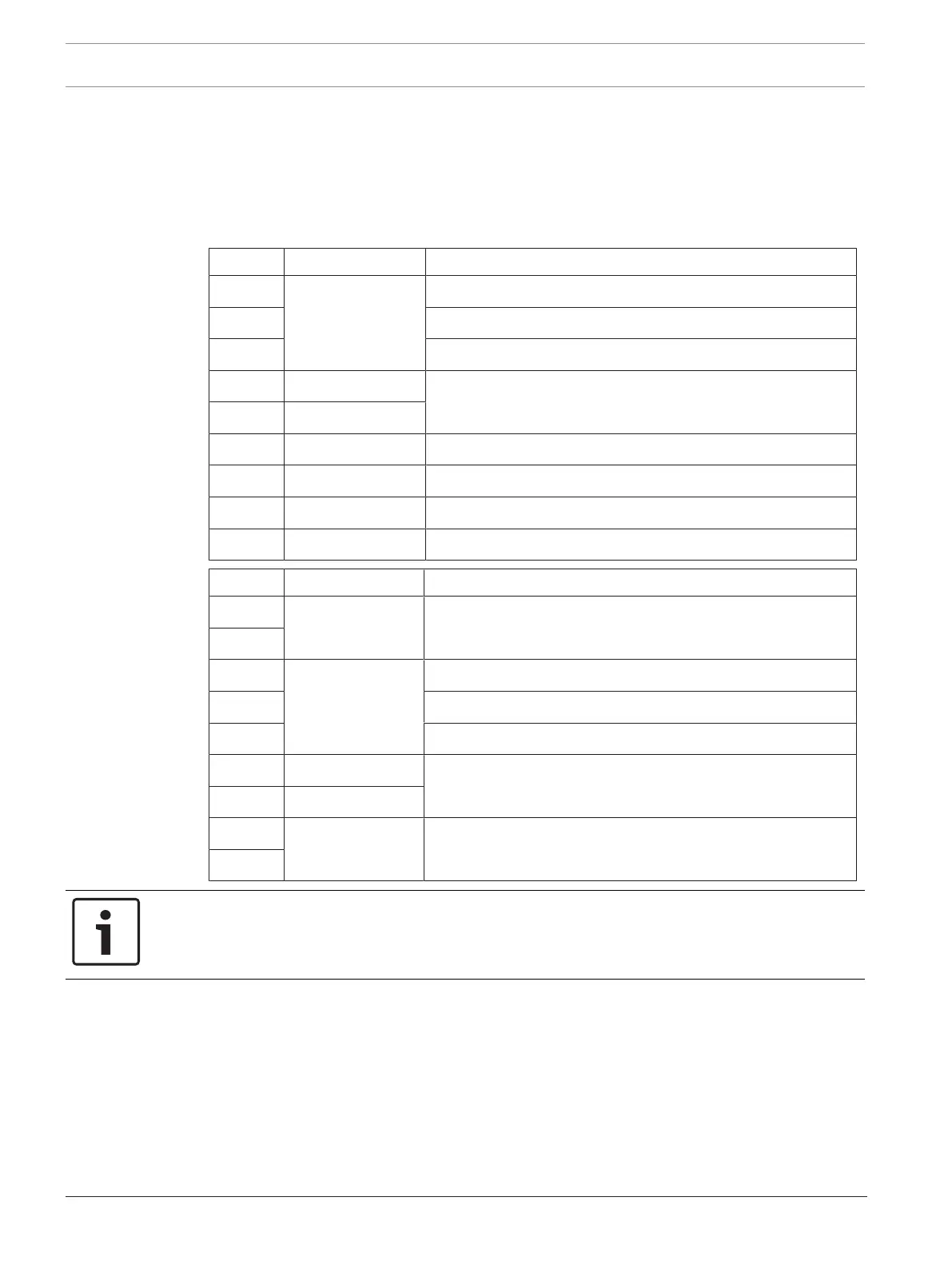
Terminal Terminal block X6 Function
1 Al 1 NO contact for 1st alarm relay
2 C contact for 1st alarm relay
3 NC contact for 1st alarm relay
4 + Ext. Displ.1 Remote indicator for 1st detector module
5 - Ext. Displ.1
6 + Reset +24V reset input
7 - Reset 0V reset input
8 + 24V +24V power supply
9 - 24V 0V power supply
Terminal Terminal block X7
1 Fault 2 Fault contact for 2nd detector module
2
3 Al 2 NO contact for 2nd alarm relay
4 C contact for 2nd alarm relay
5 NC contact for 2nd alarm relay
6 + Ext. Displ.2 Remote indicator for 2nd detector module
7 - Ext. Displ.2
8 Fault 1 Fault contact for 1st detector module
9
Notice!
On Bosch fire panels, use R
A
820 Ohm for the alarm resistor and RE 2k2 (3k9) for the terminal
resistor.