Aspirating Smoke Detector Planning | en 49
Bosch Sicherheitssysteme GmbH Operation Guide 2018.04 | 2.0 | F.01U.130.926
Quadruple U-pipe
system
Air sampling opening Number of air sampling openings
8 16 24 32
∅ air sampling
opening in mm
a
A 3.20 2.5 2.0 2.0
B - 3.0 2.5 2.0
C - - 3.0 2.0
D - - - 2.5
a
Punch diameter of the aspiration reducing film sheet
See also
– Defining the Response Sensitivity, page 37
– Planning without filter, page 123
– Planning with air filter, page 125
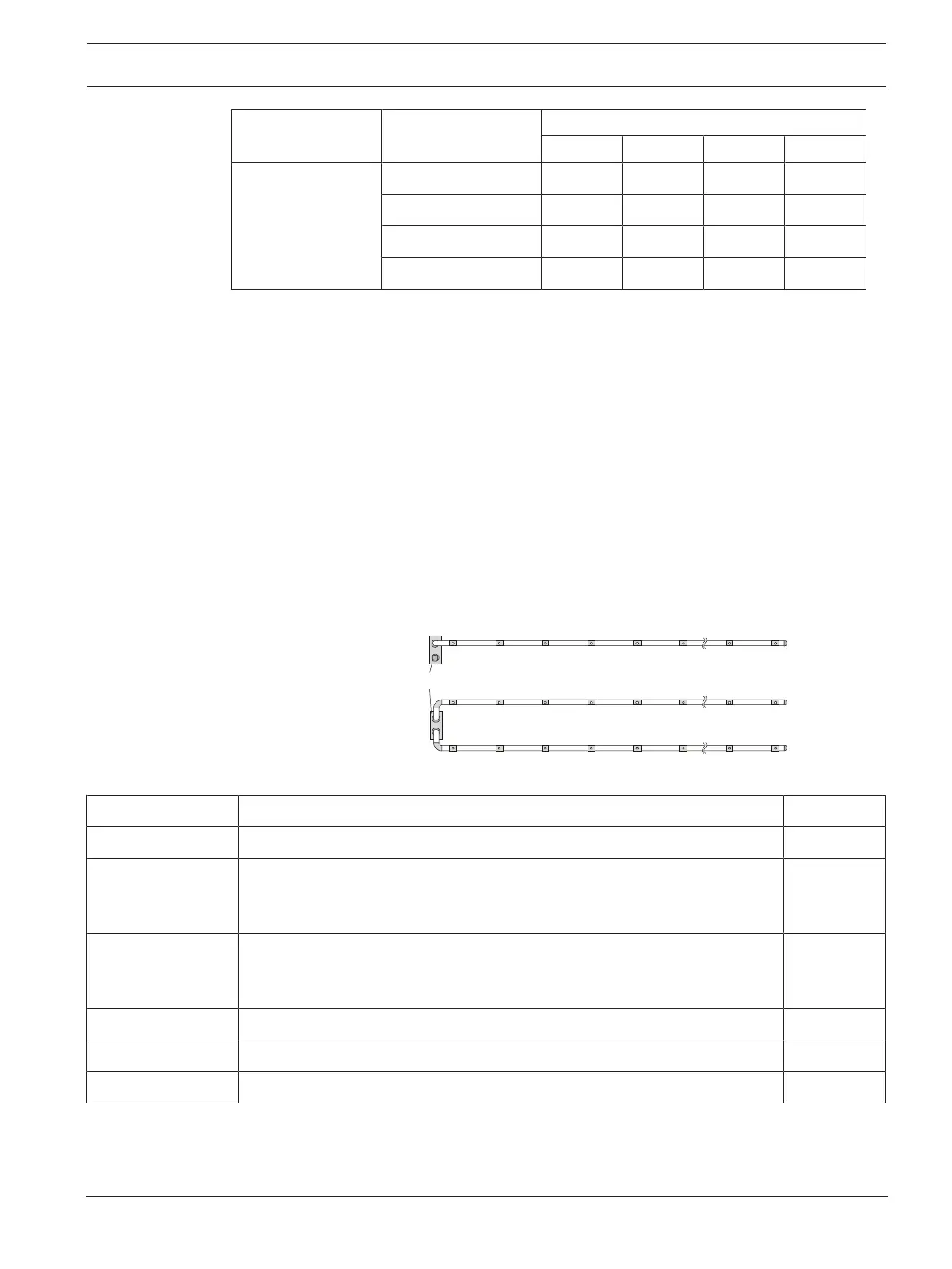
4.7 Pipe Planning for Single-Hole Monitoring
Depending on the pipe configuration, the following system parameters are used to detect a
single air sampling opening or a particular number of obstructed air sampling openings.
Planning is to be carried out according to regulations specified in Standard Pipe Planning.
Additionally, the following limiting values and opening diameters must be observed. An
additional accessory (air filter, condensate separator etc.) can have an effect on the maximum
pipe length.
I-pipe system - single-hole monitoring
1 pipe system FCS-320-
TP1 FCS-320-TT1
2 pipe systems FCS-320-
TP2 FCS-320-TT2
FAS / FCS
A
B
C D E I JF
A
B
C D E I JF
I-pipe system for space protection
Limiting values Min. distance FCS-320– 1st air sampling opening 4m
I-pipe system Max. distance FCS-320 – 1st air sampling opening 20m
Max. distance: 1st air sampling opening – last air sampling opening
– With low fan voltage
– With high fan voltage
40m
60m
Max. overall pipe length (Ø 25mm)
– With low fan voltage
– With high fan voltage
60m
80m
Min. distance between 2 air sampling openings 4m
Max. distance between 2 air sampling openings 12m
Max. number of air sampling openings (n) per pipe system 10