Aspirating Smoke Detector Planning | en 69
Bosch Sicherheitssysteme GmbH Operation Guide 2018.04 | 2.0 | F.01U.130.926
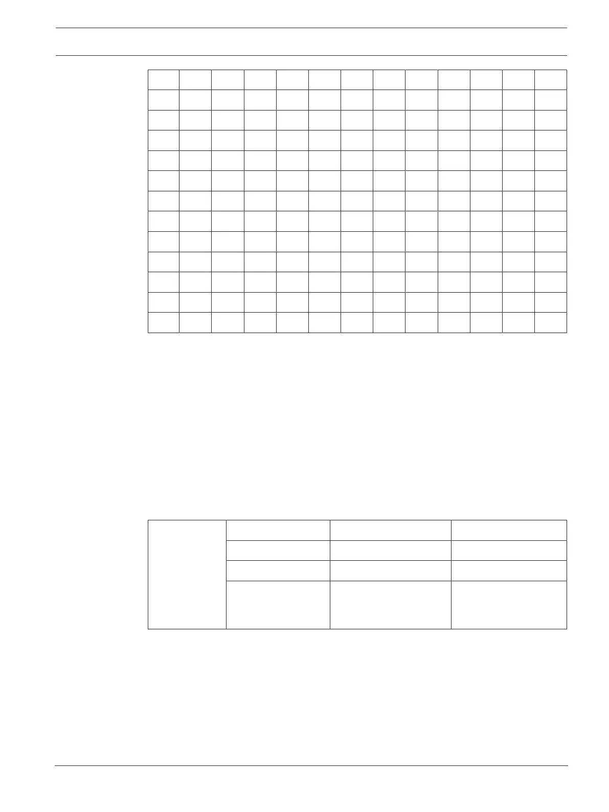
N 7.0 3.6 3.0 3.0 2.5 2.5 2.5 2.5 2.5 2.5 2.5 2.0
O a 7.0 3.6 3.6 2.5 2.5 2.5 2.5 2.5 2.5 2.5 2.0
P - a 7.0 3.6 3.0 2.5 2.5 2.5 2.5 2.5 2.5 2.5
Q - - a 6.0 3.6 2.5 2.5 2.5 2.5 2.5 2.5 2.5
R - - - a 6.0 3.0 2.5 2.5 2.5 2.5 2.5 2.5
S - - - - a 6.0 3.0 2.5 2.5 2.5 2.5 2.5
T - - - - - a 6.0 3.0 2.5 2.5 2.5 2.5
U - - - - - - a 6.0 3.0 2.5 2.5 2.5
V - - - - - - - a 6.0 3.0 2.5 2.5
W - - - - - - - - a 6.0 3.0 2.5
X - - - - - - - - - a 6.0 3.0
Y - - - - - - - - - - a 6.0
Z - - - - - - - - - - - a
a = Acceleration openings = 7.0 mm
See also
– 2. Option: reducing the number of air sampling openings, page 61
4.11 Planning for Forced Airflow
Monitoring the air-conditioning ducts
Air-conditioning units are broken down into low and high-speed units (see table below). The
details provided in this chapter apply only to low-speed units. There are no adequate empirical
values available for high-speed units. Hence, smoke trials must be executed for air-
conditioning ducts with flow speeds above 10m/s, in order to determine optimal response
behavior.
Air-
conditioning
ducts
Low-speed units High-speed units
Flow speed Maximum 6 to 10 m/s > 10m/s
Duct cross-section Large Small
Difference pressures
along the flow
direction
Low High
The speed distribution in an air-conditioning duct appears as follows: