70 en | Planning Aspirating Smoke Detector
2018.04 | 2.0 | F.01U.130.926 Operation Guide Bosch Sicherheitssysteme GmbH
1
v
1
v
1 >
v
2 >
v
3 >
v
4
v
2
v
3
v
4
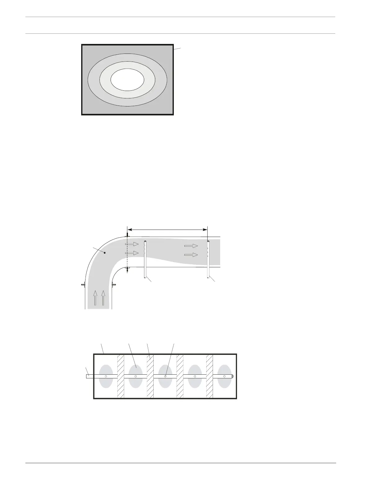
Speed distribution in an air-conditioning duct
1 Air-conditioning duct
V
1
-V
4
Flow speed
Aspiration
To achieve optimal detection results, the pipe system should be organized into the areas v
1
tov
3
Installation location of the pipe system
The exhaust duct should be selected as the installation location of the pipe system, as far as
possible away from the sound dampers, air baffles and bends. The distance from obstacles of
this kind should be at least three times the smallest duct diameter.
If it is absolutely essential to install the pipe system directly behind air baffles, sound dampers
or bends; the main speed ranges must be monitored (see Installation location of the pipe
system , page 70/Installation location of the pipe system , page 70).
Direction change of the duct without air baffles
1 Main speed range
2 Exceptional arrangement of
the pipe system (if distance
of 3xd
min
cannot be
observed)
3 Typical pipe system
arrangement
d
min
Smallest duct diameter
Sound dampers in a duct
1 Smoke aspiration pipe
2 Air-conditioning duct
3 Main speed range
4 Sound dampers
5 Bore
When installing a pipe system in air-conditioning ducts, the following must be observed:
– Since the FCS-320 and the pipe system are located in different pressure ranges, an air
return pipe (see Installation location of the pipe system , page 70) must be provided.
– The pipe entries into the duct must be airtight.
– The portion of the pipe system that is outside the duct must be sealed airtight.