108 en | Commissioning Aspirating Smoke Detector
2018.04 | 2.0 | F.01U.130.926 Operation Guide Bosch Sicherheitssysteme GmbH
B
A
ø 7,0 mm
ø 4,2 mm
ø 4,6 mm
1
3
2
3
4
5
1
2
FAS-420 series
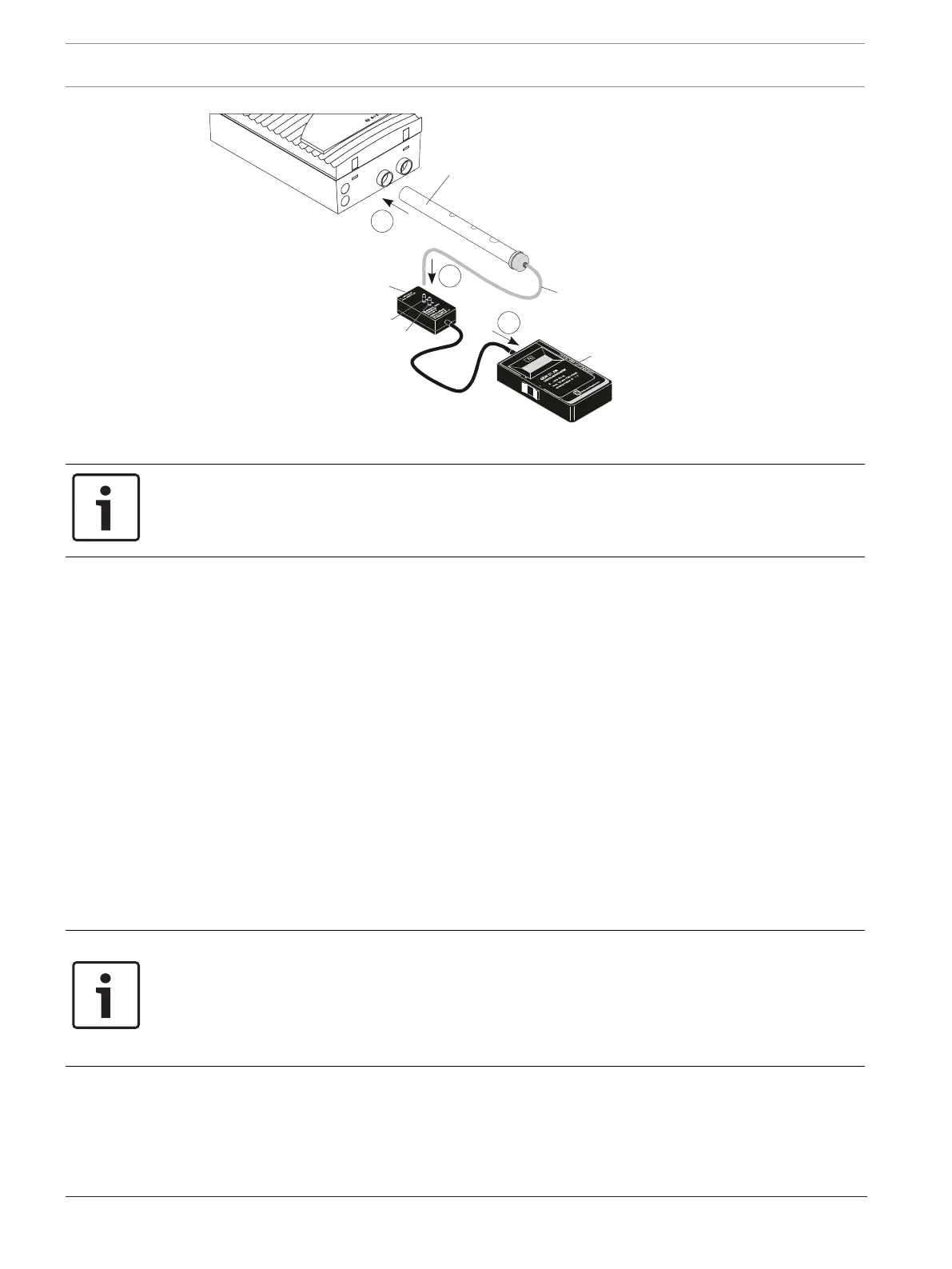
Testing the functionality of the FCS-320
1 Test pipe
2 Aspiration borings
3 Pressure measuring hose
4 Adapter
5 Digital pressure gauge
A/B Adapter connection
Notice!
For the FCS-320-TP2 and FCS-320-TT2, the preparation for the function test (see above) and
the following functional test (steps 1–7) are to be carried out for both detector modules and/
or both pipe systems.
7.6.2 Conducting the Functional Test
The functional test can be conducted with or without a digital pressure gauge. The complete
test is described below. If the test on the FCS-320 reveals deviations from the described
procedure, the unit or its airflow sensor is defective.
– Make sure that the aspirating smoke detector has been operating for at least 30minutes.
– Close all the test pipe’s aspiration borings with some duct tape. After a few seconds, the
LED flash code on detector module I and detector module II must signal an obstruction.
After a short run-up time, the negative pressure must lie within the following range:
– Fan voltage 6.9V: 250Pa to 310Pa
– Fan voltage 9V: 460Pa to 530Pa.
– Open all of the test pipe's aspiration borings. After a few seconds, the flash code of the
LED must go out.
– Remove the test pipe. The LED flash code on detector module I and detector module II
must signal a breakage.
– Reconnect the test pipe to the device. After a few seconds, the flash code of the LED
must go out.
Notice!
A pipe breakage or pipe obstruction is indicated by a flash code via an LED on the detector
module (see Section7.2Flash Code Table, page94):
Breakage: 3 x flashes
Obstruction: 2 x flashes
The corresponding flash code is repeated every two seconds.
DIAG diagnostic software
The DIAG Diagnostic Software can be used to track airflow values during the function test.
Save all diagnostics data as a file. To be able to compare the data read out, save each file
under a different file name.
Information for installing the diagnostic software can be found in Preparation, page 103.