Aspirating Smoke Detector Installing the Aspirating Smoke Detector | en 79
Bosch Sicherheitssysteme GmbH Operation Guide 2018.04 | 2.0 | F.01U.130.926
– Carefully pull the display board connection cable from the motherboard ("DISPLAY"
connection) and remove the housing cover. Once the unit is installed, fix the cover with a
service clip.
Notice!
FCS-320-TP2 and FCS-320-TT2 variants:
These unit types are factory prepared for the installation of two detector modules:
The fan covers for both aspiration pipes are removed.
The two pipe system connections are cut out.
The pin pair on jumper BR1 is open (see Number of Detector Modules).
– Spread the brackets provided for fixing the detector module slightly apart.
– Carefully insert the detector module until you hear it click into place. Make sure that the
used detector module is fixed tightly and securely by the bracket by additionally pushing
together the brackets by hand.
– Connect detector module 1 to the "HEAD1" connection on the motherboard using the
flatband cable. FCS-320-TP2 and FCS-320-TT2 variants: Connect detector module 2 to the
"HEAD2" connection on the motherboard using the flatband cable.
– Reconnect the display board cable to the "DISPLAY" connection on the motherboard.
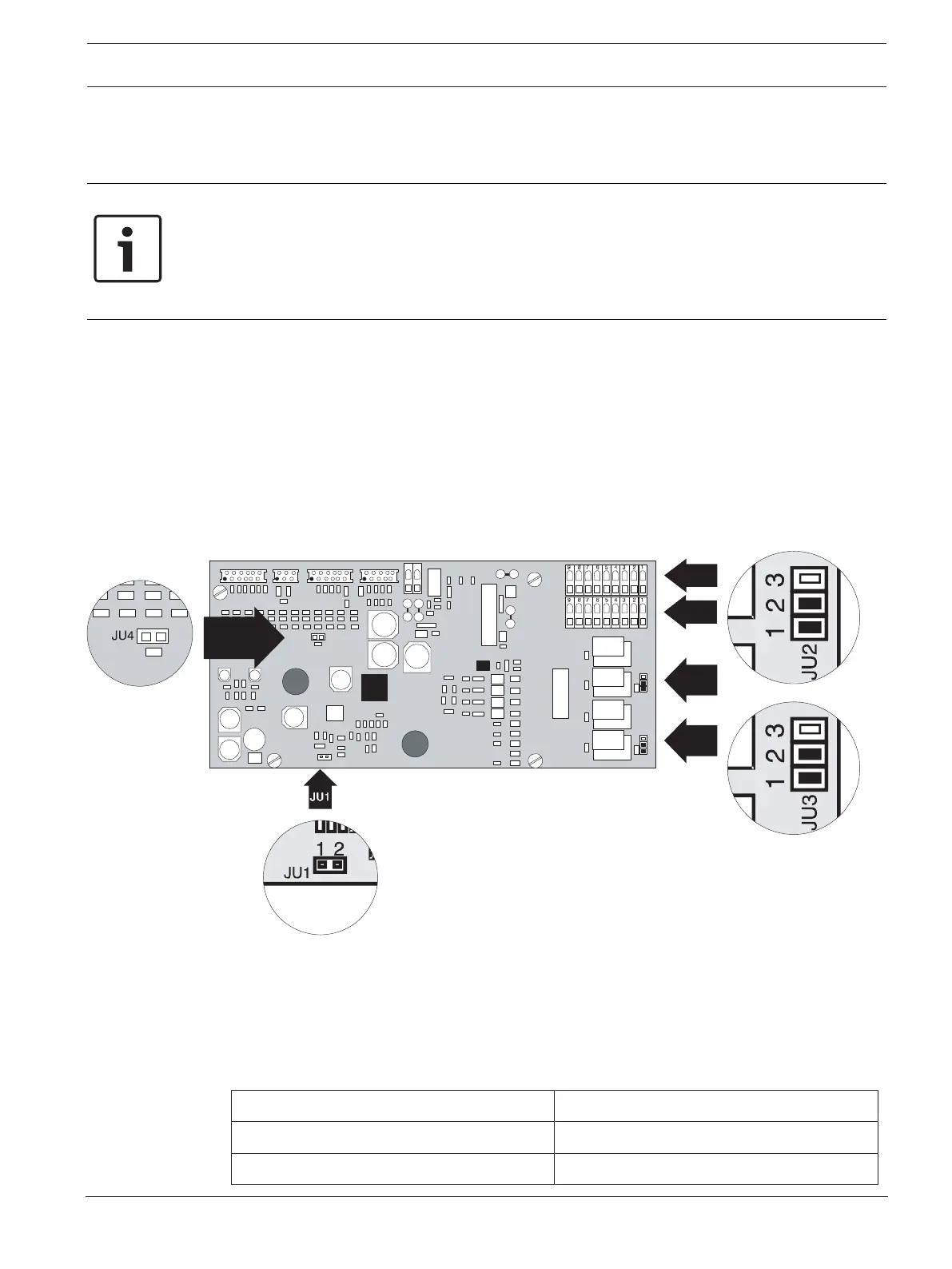
5.3 Settings on the Unit Motherboard
21
2
U
J
3
2UJ
21
3
U
J
3
3UJ
HEAD 1 HEAD 2DIAG DISPLAY
X5
2 1
2UJ
3UJ
2 31
2UJ
2 31
X1 X2 X3 X4
JU4
1 2
JU1
JU1
1 2
4UJ
JU4
6X
7X
Figure5.1: Settings on the motherboard
5.3.1 Setting the Fan Voltage
The standard fan voltage setting is 6.9V. In critical applications, the fan voltage may be
switched to 9V. This increases the transport speed in the pipe system, thus achieving faster
detection with longer pipe lengths.
To switch to 9V, pull out jumper JU1.
Fan voltage Jumper JU1, pin no. 1+2
6.9V X
9V O