Aspirating Smoke Detector Installing the Aspirating Smoke Detector | en 85
Bosch Sicherheitssysteme GmbH Operation Guide 2018.04 | 2.0 | F.01U.130.926
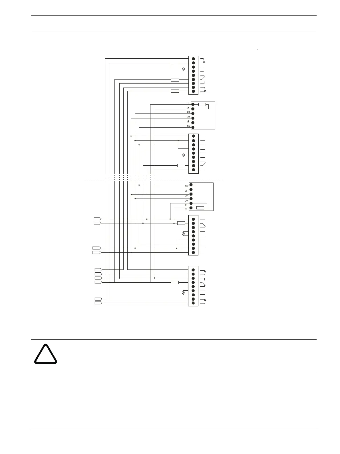
5.5.3 Electrical connection of the reset board
L4 +
+24V
0V
R
E
R
X6
7
8
6
5
4
3
2
1
_
+
9
_
+
_
+
L1 +
R
_
+
_
+
_
+
_
+
X7
_
+
X6
2
1
3
4
5
6
7
8
9
5
4
6
7
8
9
3
2
1
R
L2 -
L2 +
7
8
6
5
4
3
2
1
9
X7
R
1
2
3
4
5
6
R
ER
1)
- Ub
+ Ub
+
-
1
2
3
4
5
6
R
ER
1)
- Ub
+ Ub
+
-
L3 +
L3 -
L4 -
E
R
L1 -
FCA-32
0-Reset
FCA
-320-Reset
FCS-320-TP/TT
FCS-320-TP/TT
5.6 Connection to the Fire Panel
5.6.1 Electrical Connection
Caution!
Switch off the unit before carrying out any connection work!
Proceed as follows to prepare the electrical connections:
– Using a screwdriver, carefully punch out the required cable entry points of the housing
(max. 5 x M20 and 2 x M25).
– Fit the cable entry point(s) as required with M20 or M25 connections by pushing them
into the cable entries. 2xM25 and 1xM20 are supplied in the pack.