EasyManuals Logo

Bosch HPC 400 Installation Instructions For Contractors

Bosch HPC 400
30 pages
To Next Page IconTo Next Page
To Previous Page IconTo Previous Page
Page #4 background imageLoading...
Page #4 background image
Product
information
3
Product
information
3.1
Product
description
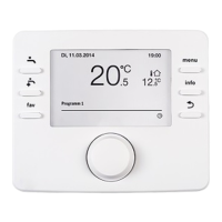
The
user
interface
is
used
to
control
a
heating
system
with
a
maximum
of
four
heating/cooling
circuits
and
a
cylinder
primary
circuit
for
DHW
heating,
solar
DHW
heating
and
solar
central
heating
backup.
The
user
interface
incorporates
a
time
program:
-
Heating
systems
:
For
each
heating
circuit,
2
time
programs
with
2
switching
times
per
day.
If
a
buffer
cylinder
is
not
installed,
heating
circuits
2
...
4
can
only
switch
to
heating
mode
when
heating
circuit
1
is
in
heating
mode
.
-
Domestic
hot
water
:
One
time
program
for
DHW
heating
and
one
time
program
for
the
DHW
circulation
pump
,
each
with
6
switching
times
per
day
.
The
user
interface
displays
information
about
the
heat
source
and
heating
system
and
is
used
to
change
the
settings.
After
operating
for
1'h
hour
,
the
user
interface
has
a
power
reserve
of
at
least
8
hours
.
If
the
power
failure
lasts
longer
than
the
power
reserve,
the
time
and
date
will
be
deleted.
All
other
settings
are
saved.
The
functional
scope
and
thus
the
menu
structure
of
the
user
interface
are
determined
by
the
structure
of
the
system.
Your
attention
is
drawn
to
the
importance
of
the
system
structure
in
the
relevant
places
.
The
adjustment
ranges
and
default
settings
may
differ
from
the
information
in
these
instructions.
Certain
menu
items
are
specific
to
certain
countries
and
are
only
displayed
if
the
country
in
which
the
heat
pump
is
installed
has
been
set
accordingly
on
the
user
interface
.
3.1.1
Control
types
The
following
main
control
types
are
available
for
the
heating
system:
Weather-compensated
:
Automated
control
of
the
flow
temperature
based
on
the
outside
temperature
.
Weather-compensated
with
the
influence
of
the
room
temperature:
Automated
control
of
the
flow
temperature
based
on
the
outside
temperature
and
room
temperature.
Installation
of
a
remote
control
in
the
reference
room
is
required
.
If
cobling
is
active,
a
set
constant
temperature
is
maintained.
Observe
the
further
information
on
the
control
types
and
settings
that
affect
how
the
system
is
controlled
(7
Chapter
6.
3,
page
17)
.
3.2
Important
notices
on
usage
&
WARNING:
Risk
of
scalding!
I
If
t~ermal
disinfection
ha
.s
been
activated
to
avoid
legion
ella,
the
hot
water
IS
heated
once
to
in
excess
of
65
·C
.
The
factory
setting
for
the
hot
water
temperature
is
60
·C.
There
is
a
risk
of
scalding
at
the
draw-off
points
if
the
temperature
is
set
higher
than
this
.
~
Make
sure
that
a
mixing
device
is
installed.
&
NOTICE:
Floor
damage!
I
~
For
underfloor
heating
systems,
make
sure
that
the
maximum
temperature
for
the
floor
type
in
question
is
not
exceeded
.
~
If
necessary,
connect
an
additional
temperature
switch
at
the
voltage
input
of
the
respective
pump
or
to
one
of
the
external
inputs
of
the
heat
pump
.
Only
products
from
the
same
distributor
may
be
used
within
the
BUS
systero
·
BOSCH
3.3
Additional
accessories
For
precise
information
regarding
suitable
accessories
,
refer
to
the
catalogue
.
Function
modules
and
user
interfaces
of
the
EMS
2
control
system
:
User
interface
CR
10
as
simple
remote
control
User
interface
CR
10 H
as
simple
remote
control
with
option
to
measure
relative
humidity
(heating/cooling
circuits)
MM
100
:
Module
for
heating/cooling
circuits
with
mixing
valve
MP
100
:
Module
for
a
swimming
pool
with
heating
via
the
heat
pump
MM
100
:
Module
for
solar
DHW
heating
MS
200
:
Module
for
extended
solar
systems
.
Applicability
of
these
instructions
to
EMS
2-capable
modules
These
instructions
also
apply
to
the
user
interface
when
used
in
conjunction
with
heating/cooling
circuit
module
MM
100
(accessory)
.
Additional
setting
options
may
be
found
in
some
menus,
if
your
heating
system
is
equipped
with
alternative
modules
(e
.g.
solar
module
MS
100
.
accessory)
.
These
setting
options
are
explained
in
the
technical
documentation
of
the
modules
.
4
HPC
400 - G 720821
772
(2017/07)

Other manuals for Bosch HPC 400

Questions and Answers:

Question and Answer IconNeed help?

Do you have a question about the Bosch HPC 400 and is the answer not in the manual?

Bosch HPC 400 Specifications

General IconGeneral
BrandBosch
ModelHPC 400
CategoryControl Panel
LanguageEnglish

Related product manuals