56 en | Connections MAP 5000
2016.06 | 17 | F.01U.168.332 Installation manual Bosch Sicherheitssysteme GmbH
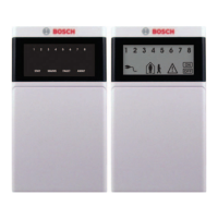
3.10.3 Programming instructions for ISP-EMIL 120
If wiring is performed in accordance with Connecting the LED panel to ISP-EMIL 120, page 55,
the predefined device LED table can be used for simple programming of the ISP-EMIL 120
expansion module with the program RPS for MAP.
Inputs Function
PL1 Key switch ’Reset’
PL2 Key switch ’Motion Detector Test’
PL3 Free
PL4 Tamper switch
PL5 Free
PL6 Free
Outputs Function
S1 Trouble
1
S2 Intrusion/tamper alarm
1
S3 Walk test, motion detector test
1
S4 Area disarmed
1
Tab.3.2: Programming for ISP-EMIL 120
1
The following applies for VdS: Function must not be removed
3.11 Final power connections
1. Connect AC wires to the AC terminal block.
2. Connect the battery wire leads to the batteries.
Do not connect the batteries to the power supply at this time.
3. Switch the AC breaker on.
4. Ensure that there are no power-related trouble conditions.
Warning!
Ensure that the AC LED indicator on the power supply turns on steady before you connect the
battery terminal to the power supply.

 Loading...
