12 en | System overview INTEGRUS
2023-01 | V01 |
User manual
Bosch Security Systems B.V.
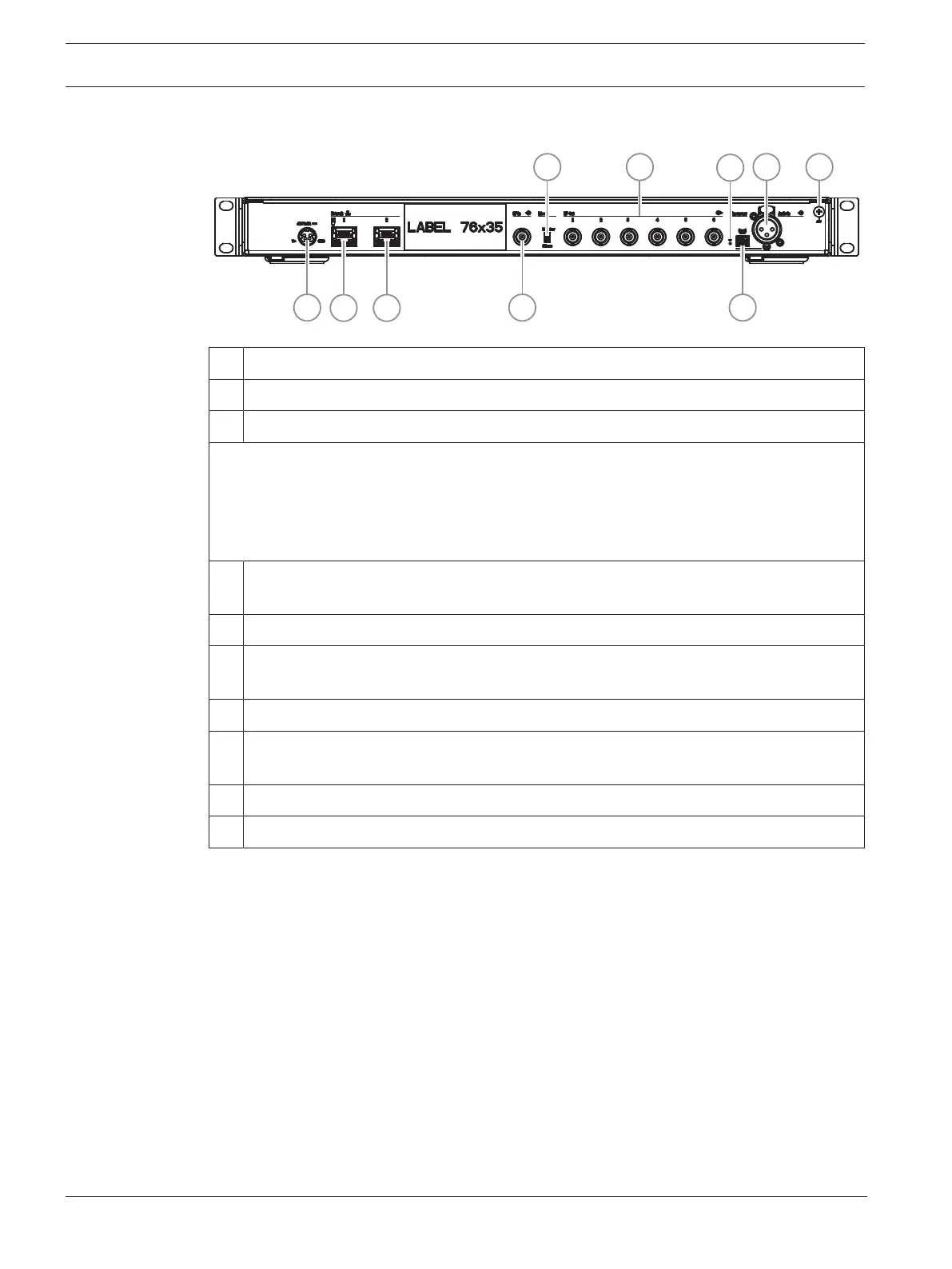
Rear view
1 Power supply.
2 Network 1: Supports powering through DICENTIS or PoE.
3 Network 2: Supports powering through DICENTIS.
The LEDs next to the network connectors share the same behavior:
– Red/green or amber/green blinking: The transmitter needs to be upgraded.
– Yellow: Network activity present.
– Green: Network speed of 1GB.
– Orange: Network speed of 100MB.
4 HF In: Slave input. BNC connector that accepts an HF signal from a transmitter in
Master mode.
5 Mode Master/Slave switch. The default mode is Master.
6 HF Out 1-6: Six high-frequency BNC connectors, used to connect to the radiators. Up to
30 radiators can be connected in a loop to each output.
7 Reset button: Press and hold for 10 seconds to reset the device to factory settings.
8 Emergency terminal block socket for distribution of emergency messages to all
channels.
9 Audio In: XLR socket distribute audio to all channels.
10 Chassis ground.









 To Next Page