22 en | Planning INTEGRUS
2023-01 | V01 |
User manual
Bosch Security Systems B.V.
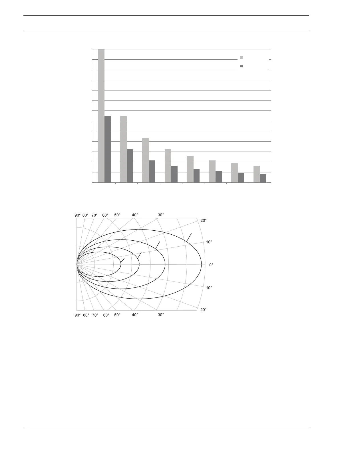
0
200
400
600
800
1000
1200
1400
1600
1800
2000
2200
2400
2600
1 2 3 4 5 6 7 8
m
2
Figure4.3: Total coverage area of LBB4511/00 and LBB4512/00 for 1 to 8 carriers
Figure4.4: Polar diagram of the radiation pattern for 1, 2, 4 and 8 carriers
Footprint
The cross section of the 3-dimensional radiation pattern with the floor of the conference
venue is known as the footprint (the white area in the following three figures). This is the floor
area in which the direct signal is strong enough to ensure proper reception, when the receiver
is directed towards the radiator. As shown, the size and position of the footprint depends on
the mounting height and angle of the radiator.
 Loading...