3.4 Frame shape and installation positions
Motor design B05
IM B5 IM V1 IM V3
Flange attachment on the
drive side of the flange
Flange attachment on the
drive side of the flange,
drive side facing down
Flange attachment on the
drive side of the flange,
drive side facing up
Tab. 3-3: Allowed installation types acc. to EN 60034-7:1993
Motor damage due to penetration of liquids!
If motors are attached according to IM V3, fluid present at the output shaft
over a prolonged time may penetrate and cause damage to the motors.
Ensure that fluid cannot be present at the output shaft.
3.5 Installation space
Self-cooling of the motor should not be prevented due to the installation situa‐
tion.
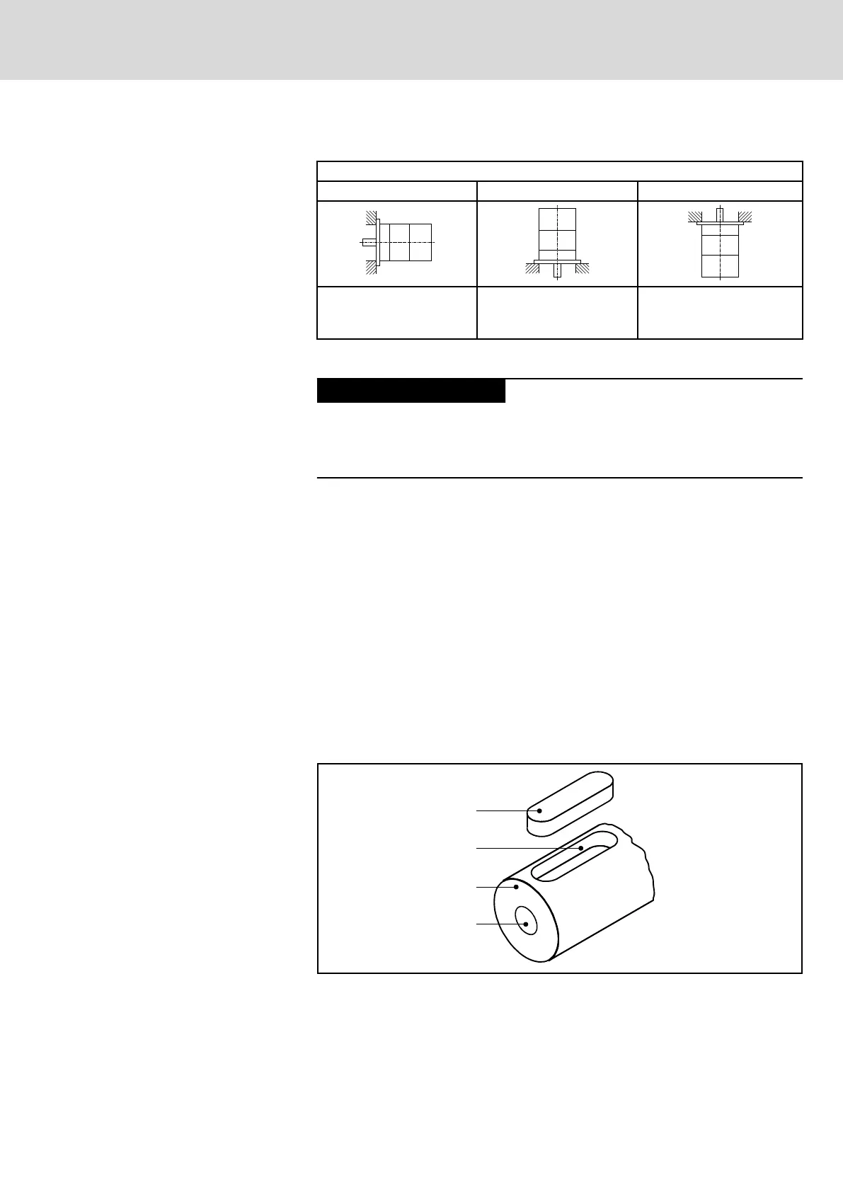
3.6 Output shaft
Smooth shaft
MSM motors offer a non-positive shaft-hub connection without play with ex‐
cellent running smoothness. Use clamping sets, clamping sleeves or tension‐
ing elements to couple the machine elements to be driven.
Labeling within motor type: MSM....-....-..-..-.H
Shaft with keyway
MSM motors with keyway allow form-locking transmission of torques with
constant direction and low requirements on the shaft-hub connection. The
keyway is not in the scope of delivery.
Labeling within motor type: MSM....-....-..-..-.L
① Key
② Keyway
① Motor shaft
① Centering hole
Fig. 3-1: MSM Output shaft with keyway
DOK-MOTOR*-MSM********-DA05-EN-P Bosch Rexroth AG 9/61
Synchronous Servomotors MSM
Operating conditions