5 Technical data
5.1 Basics
Operation modes
The motors are documented according to the test criteria and measuring
methods of EN 60034-1. The specified characteristic curves correspond to
operating modes S1.
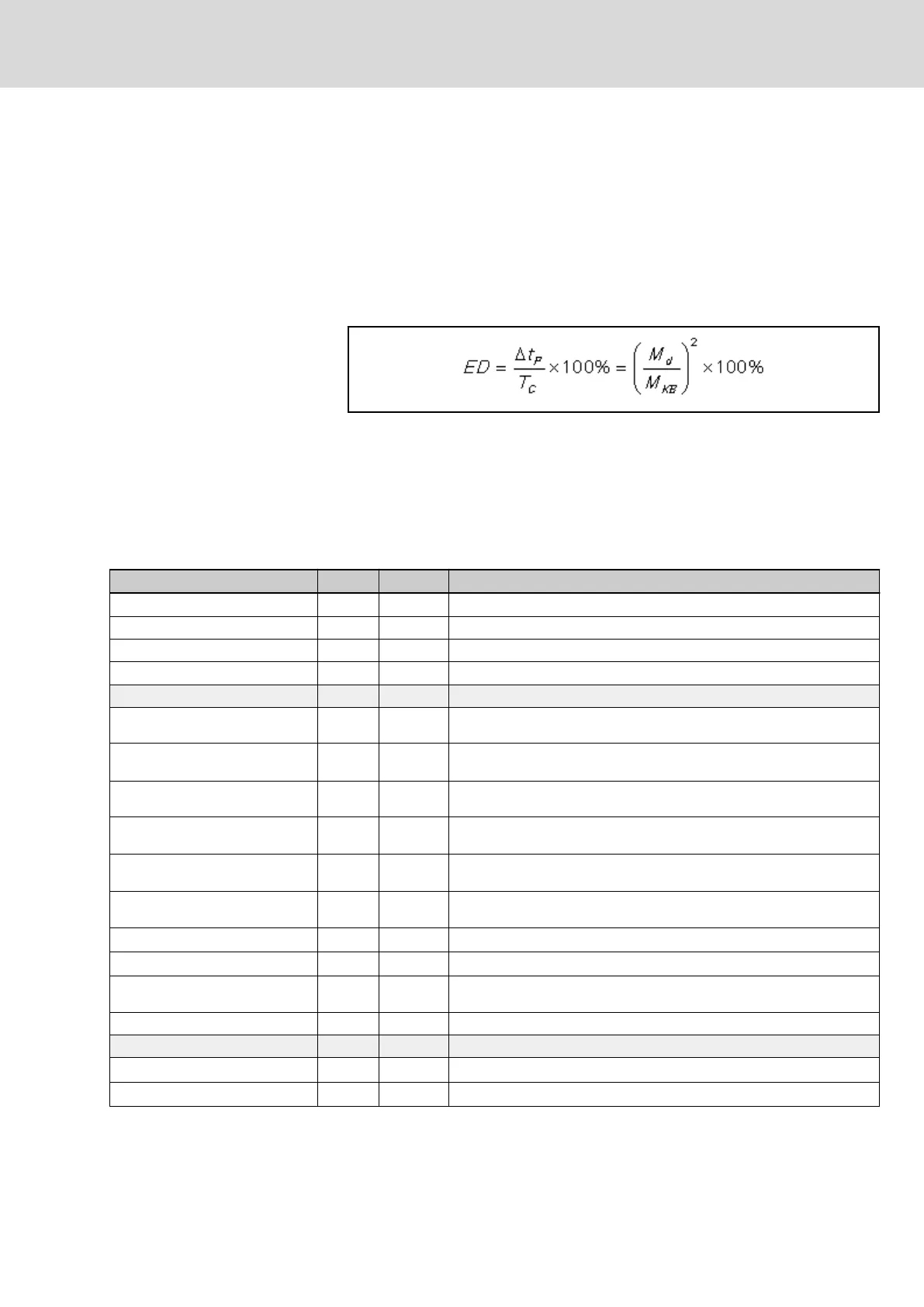
Duty cycle
Operating mode S6 is only available with duty cycle DC ≤100%. The duty cy‐
cle is calculated:
ED Duty cycle
T
C
Cycle duration
ΔT
P
Operating time with constant load
M
d
Continuous torque
M
KB
Short-time service torque
Fig. 5-1: Relative duty cycle
Definition of parameters
Designation Symbol Unit Definition
Cooling mode acc. to EN 60034-6 Short name acc. to EN
Listed acc. to UL standard (UL) UL Standard
Listed acc. to CSA standard (UL) CSA Standard
UL-Files (UL) UL File Number
Electrical parameters
Continuous torque at standstill 60 K
M
0_60
Nm
Continuous torque that can be applied to the motor output shaft at a speed
of n ≥ 0.1 Hz.
Continuous current at standstill 60
K
I
0_60(eff)
A
Phase current (crest value) of the motor M
0_60
required for the continuous
torque at standstill at a speed of n ≥ 0.1 Hz.
Maximum current
I
max(eff)
A
Maximum, temporarily permissible phase current of the motor winding with‐
out adverse effect on the permanent magnet circuit of the motor.
Maximum torque
M
max
Nm
For maximum current I
max
, for approx. 400 ms exchangeable maximum tor‐
que. The achievable maximum torque depends on the drive control unit.
Torque constant at 20 °C
1)
K
M_N
Nm/A
Ratio of generated torque to motor phase current at motor temperature
20 °C. Valid up to approx. i = 2x I
0_60
.
Voltage constant at 20 °C
2)
K
EMK_1000
V/min
-1
Root-mean-square value of the induced motor voltage at a motor tempera‐
ture of 20 °C and 1,000 revolutions per minute.
Winding resistance at 20 °C
R
12
Ohm Winding resistance measured between two phases.
Winding inductance
L
12
mH Measured inductance between two strands.
Discharge capacity of the compo‐
nent
C
dis
nF Discharge capacity
Number of pole pairs p - Number of pole pairs
Mechanical parameters
Moment of inertia of rotor
J
rot
kg*m
2
Moment of inertia of the rotor without optional holding brake.
Power wire cross-section
A
60
Minimum cross-section of the power wire to be connected on the motor
DOK-MOTOR*-MSM********-DA05-EN-P Bosch Rexroth AG 19/61
Synchronous Servomotors MSM
Technical data