Type Bearing
size DE
Bearing
size NDE
Floating
bearing
Fixed
bearing
MS2N04 6003 6001 DE NDE
MS2N05 6204 6303 DE NDE
MS2N06 6206 6303 DE NDE
MS2N07 6207 6205 DE NDE
MS2N10 6309 6306 DE NDE
MS2N13 6212 6211 DE NDE
Bearing service life
The bearing lifetime is an important criterion for
the availability of motors. The operating condi-
tions influence the bearing service life L
10h
con-
siderably.
The following boundary conditions apply to the
bearing service life L
10h
:
•
Operation within the specified permissible
loads (radial and axial force)
•
Operation within the permissible ambient
conditions (temperature range 0 … 40 °C,
vibration, and so on).
• Operation within the thermally permissible
operating characteristic curve
The bearing lifetime also depends on the service
life of the grease. A calculated grease service
life was used for the mentioned specifications,
taking into consideration the following boundary
conditions.
• Horizontal installation
• Low vibration and impact loads
•
No oscillating bearing movement < 180°
•
Mean speed according to ⮫ Table 5 “Mean
speed - basis of calculated grease service
life” on page 29:
Table 5: Mean speed - basis of calculated grease
service life
Type Mean speed
MS2N03, -04, -05, -06 ≤ 3,500 1/min
MS2N07 ≤ 3,000 1/min
MS2N10 ≤ 2,000 1/min
MS2N13 ≤ 1,800 1/min
The following standard values apply under the
specified preconditions for the 60K and 100K
operation modes:
L
10h
in case of operation after S1-60K
L
10h
= 30.000 h, in case of utilization after
S1-60K and max. load factor 95% during the
runtime.
L
10h
in case of operation after S1-100K
L
10h
= 20.000 h, in case of utilization after
S1-100K and max. load factor 90% during the
runtime.
Remark: When exceeding or not complying
with these conditions, a reduced service life is
to be expected.
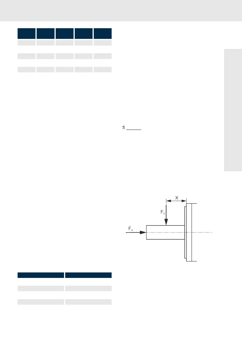
Explanation of radial and axial force
During operation, both radial and axial forces act
upon the motor shaft and the motor bearing. The
permissible radial force F
R
in distance x from the
shaft shoulder and the mean speed is specified in
the radial force diagrams.
Fig. 7: Point of action of radial force F
R
and axial
force F
A
The axial force values are the minimum per-
missible axial forces F
A
without limitations. A
detailed dimensioning is only possible if more
boundary conditions are known:
About this product