10.3 Design and installation positions
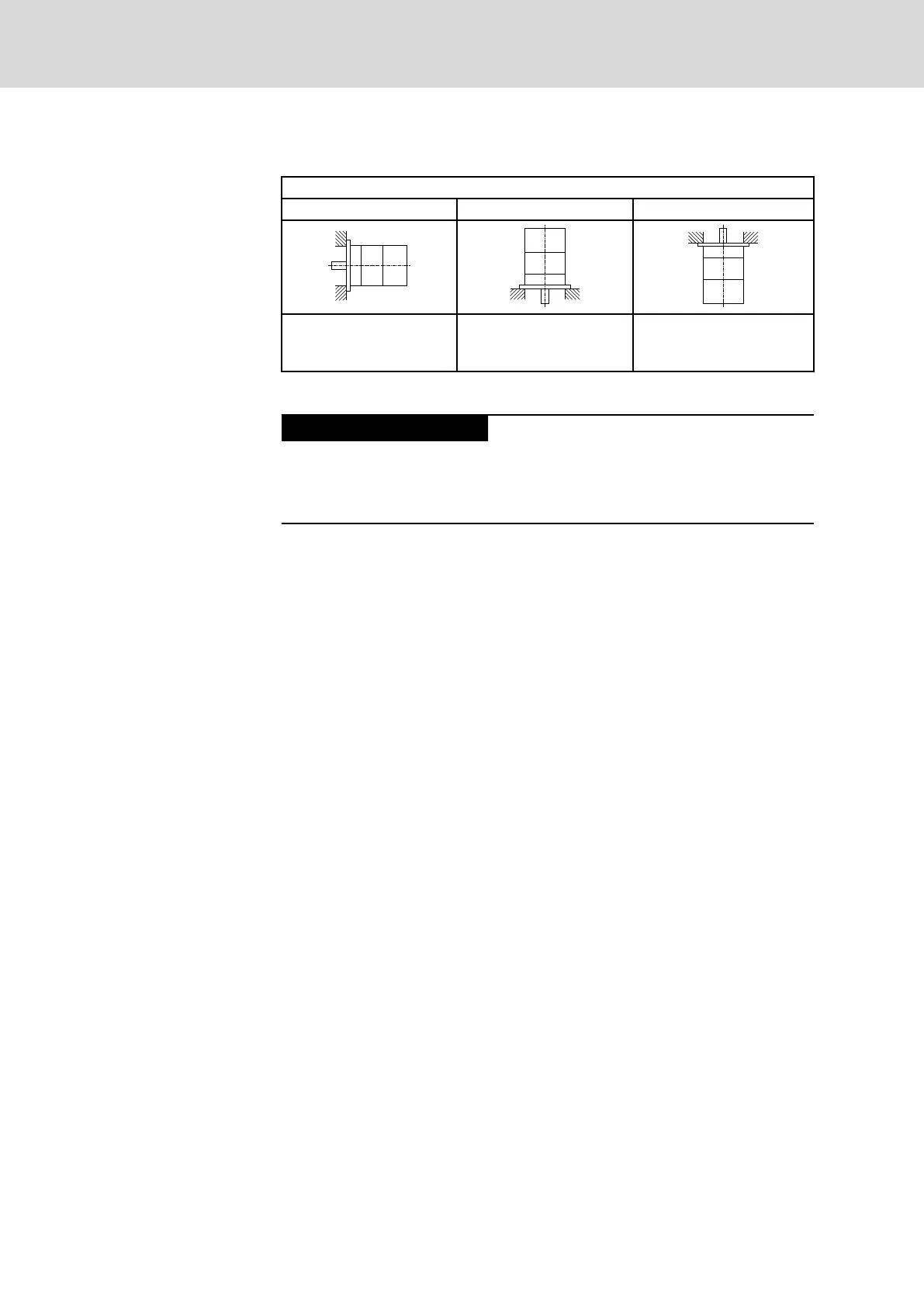
Motor design B05
IM B5 IM V1 IM V3
Flange attachment on the
drive side of the flange
Flange attachment on the
drive side of the flange,
drive side facing down
Flange attachment on the
drive side of the flange,
drive side facing up
Tab. 10-6: Permissible conditions of installation according to EN 60034-7:1993
Motor damage due to penetration of liquids!
If motors are attached according to IM V3, fluid present at the output shaft
over a prolonged time may penetrate and cause damage to the motors.
Ensure that fluid cannot be present at the output shaft.
Bosch Rexroth AG DOK-MOTOR*-MSK*EXGIIK3-PR09-EN-P120/175
Synchronous Servomotors MSK For Potentially Explosive Areas
Operating conditions and application notes






 To Next Page