14/40 Information on this product
Bosch Rexroth AG, VT-VSPA2-1-2X/V0/T., RE 30110-B/11.2012
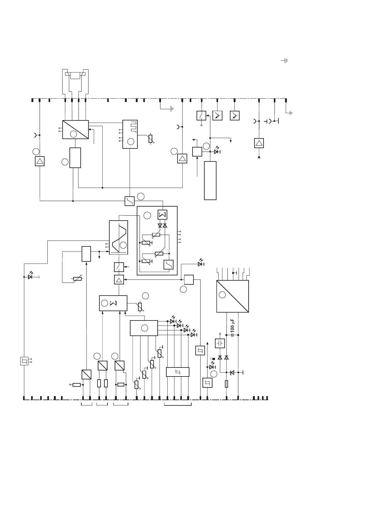
5.2.1 Block diagrams/pin assignments of the amplifier card
Fig. 1: Block diagrams/pin assignments of the amplifier card VT-VSPA../T1
1 Power supply unit
2 Differential input
3 Current input
4 Command value selec-
tionlogic
5 Zero point setting
6 Command value summation
7 Command value inversion
Ramp on/off
External ramp
time
Command value 5
± 10 V
Command
value call-ups
Command value
6 4-20 mA
Inversion
enable
Operating
voltage
Command value 4
Command value 3
Command value 2
Command value 1
Enable
Error detection
Enable
Reserved
Actual current value
Reserved
Ready for
operation
+10 V/25 mA
–10 V/25 mA
M0
System earth
Measure-
ment signal
ramptime
Reserved
Internal command value
Solenoid b
Solenoid a
8 Enable function
9 Ramp generator
10 Characteristic curve
generator
11 Amplitude limiter
12 Command value output
13 Clock generator
14 Actual current val-
ueoutput
15 Current controller
16 Power output stage
17 Fault recognition
ok1 Output stage enable signal
ok2 Card monitoring
 Loading...


