Installation 25/40
RE 30110-B/11.2012, VT-VSPA2-1-2X/V0/T., Bosch Rexroth AG
Before commencing with the adjustment work, the system-specific wiring must have
been completed.
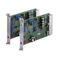
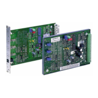
Plug jumpers "J1" to "J10" according to the application in such a way that the
associated bridge is either open or closed. Please refer to data sheet RE 30110 for
setting information.
7.2 Safety regulations
• The amplifier card may only be installed by trained and qualified experts in accor-
dance with the generally valid electrical engineering rules.
• You may only insert the amplifier card into a card holder/rack or remove the ampli-
fier card out of a card holder/rack if the supply lines to the card are de-energized.
• Do not use silicone-containing sealing, adhesive, or insulating agents.
7.3 Installation conditions
A suitable power supply unit for the amplifier card is the type VT-NE30-1X, see data
sheet29929.
▶ Prior to installing the card, ensure that all jumpers of the amplifier card are
correctly plugged.
▶ Only use measuring instruments with an internal resistance (Ri) > 100 kΩ
formeasurements.
▶ For the assembly, observe the notices regarding applied standards and applica-
tion conditions in the data sheet.
▶ Use low-capacitance cables.
▶ If possible, design the cable connections without intermediate terminals.
▶ The distance from the place of installation of the card to aerial lines, radios, and
radar systems has to be 1 m at least.
▶ Do not lay solenoid and signal lines near power cables.
▶ For solenoid lines up to a length of 50 m, use the cable type LiYCY 1.5 mm². With
greater lengths, please contact us!
▶ No plug-in connectors with free-wheeling diodes or LED indicators must be used
for connecting the solenoid conductors to the valve.
▶ Always shield command value lines. Connect shielding to "PE" on the card-side.
▶ The system earth is a main component of the amplifier card's EMC protection. It
is intended to eliminate interferences which are transported via the data and sup-
ply voltage lines. However, this is only possible if the system earth itself does not
introduce interferences into the amplifier card. Recommendation: Also shield the
solenoid lines.
If the differential input is used, both inputs must always be connected or
disconnected at the same time.
▶ Use relays with gold-plated contacts for switching command values (low voltages,
low currents).
• Electric signals taken out via control electronics (e. g. the "ready for operation"
signal) must not be used for switching safety-relevant machine functions. (See also
EN ISO 13849 "Safety of machinery - safety-related parts of control systems").
Plug jumper
Power supply unit
Important installation
instructions

 Loading...

