22/40 Information on this product
Bosch Rexroth AG, VT-VSPA2-1-2X/V0/T., RE 30110-B/11.2012
To prevent a residual step (< 1%), you have to switch off the step function
(=jumper "J4" closed) and turn the potentiometers "S+" and "S–" to the left stop.
• You can set/correct the step level "S" separately for positive and negative signals
using the potentiometers "S+" and "S–".
• You can set the maximum internal command value separately for positive and
negative signals. The potentiometers "Gw+" and "Gw–" have been installed for this
purpose. The setting range lies between 0% and 110%.
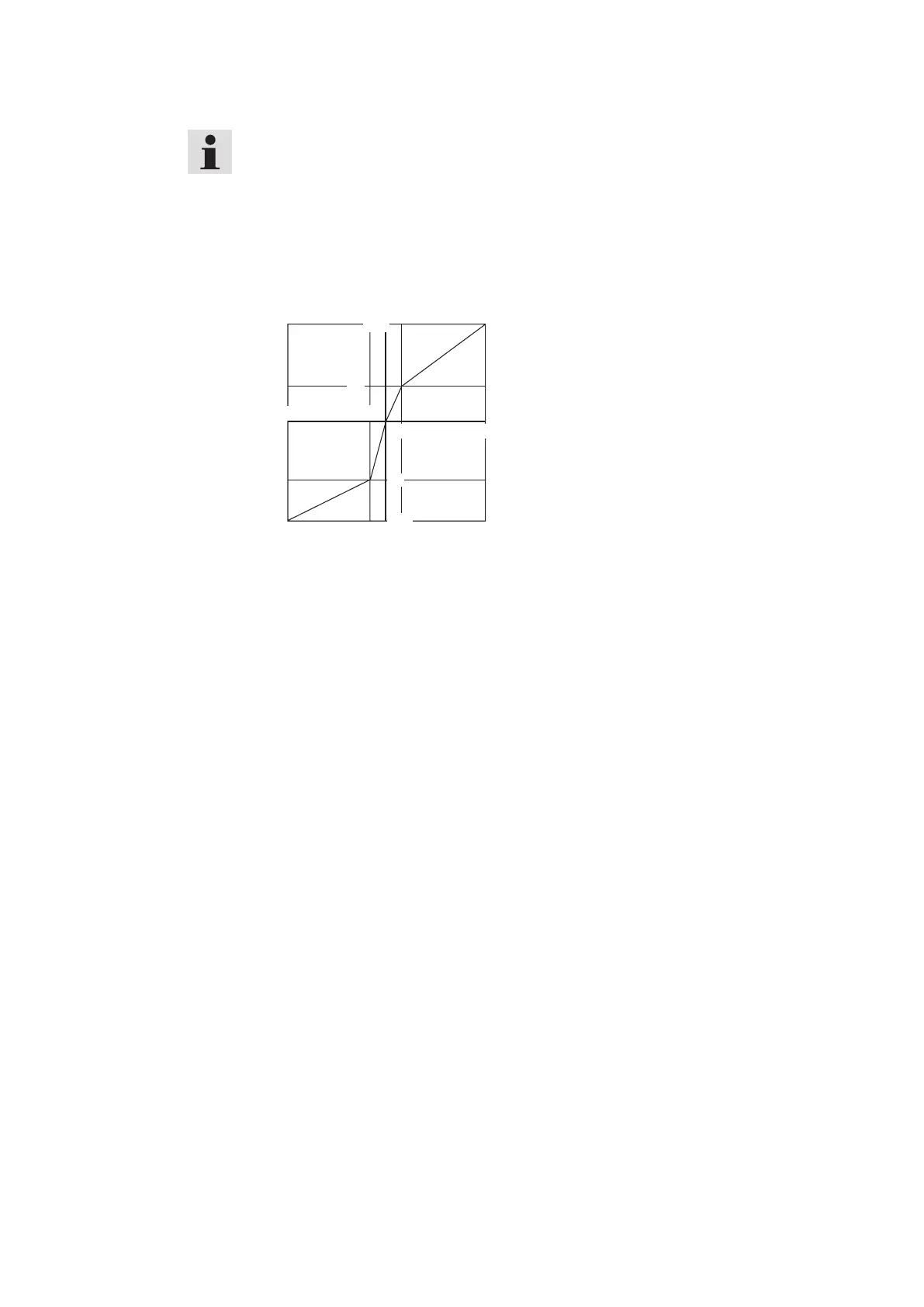
← Command value specification→
← Internal command value→
Fig. 5: Correcting the characteristic curve using the characteristic curve generator
5.2.8 Amplitude limiter [11]
From the characteristic curve generator the signal is sent to the amplitude lim-
iter[12]. Here, the internal command value is limited to approx. ±110% of the
nominal range.
5.2.9 Power output stage [16]
The power output stage [18] creates the clocked solenoid current for the proportion-
al valve. The solenoid current is limited to 2.7 A per output. The output stage outputs
are short-circuit-proof. The output stages are de-energized in case of an internal fault
signal or if the release is missing.
5.2.10 Clock generator [13]
The clock generator creates the clock frequency of the output stages. The clock sig-
nal can be switched in three basic frequency ranges using jumpers (J5, J6).
• Clock frequency for 4WRA6-2X, correctable via potentiometer "f".
• Clock frequency for 4WRA10-2X, correctable via potentiometer "f."
• Clock frequency for 4WRZ-7X, correctable via potentiometer "f", also suitable for
universal applications.
When setting the WRA valves, the frequency changes depending on the command
value and on the operating voltage.
5.2.11 Measuring sockets
A measuring socket for the command value (w) and the actual current value (I) is
installed on the front plate. The following applies: Command value ±100 % = ±10 V
Actual value ±100 % = ±2.5 V
 Loading...


