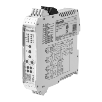
Hydraulics Bosch Rexroth AGRE 30110/05.12 VSPA2-1-2X
3/10
Function
Power supply [1]
The amplifier card has a power supply with an inrush current
limiter. This supplies all of the internal positive and negative
supply voltages. The inrush current limiter prevents inrush
current peaks caused by the smoothing capacitors in the
current output stage.
Applied command value
The internal command value signal is formed from the sum
of the external command value being applied to the differen-
tial input [2] and the command values being applied to the
summator [6] and the ramp generator.
The following is valid:
Standard
value
Current
input
Differen-
tial
input
Com.
value
socket
Flow
direction
–100% 4 mA –10 V –10 V P to B,
A to T
0 % 12 mA 0 V 0 V
100 % 20 mA 10 V 10 V P to A,
B to T
0 % < 1 mA
1)
0 V
1)
If the current input is not switched or with current com-
mand value a cable break results in an internal command
value signal 0 %.
No switching takes place between the current and voltage in-
puts. The inputs are permanently available (see pin alloca-
tion).
Command value call-ups [4]
Four command value signals „w1“ to „w4“ can be called-up.
The external command value voltages (command values 1
to 4) are either directly applied via the controlled voltage out-
puts +10 V and –10 V or via an external potentiometer. If the
command value inuts are directly applied to the controlled
volatages then the settings are done on potentiometers „w1“
to „w4“. When using external potentiometers then the internal
potentiometers act as attenuatators or limiters.
Only one call-up at the same time is possible. If more than
one call-up is activated at the same time then call-up „1“ has
the lowerst priority and call-up „4“ the highest priority.
The active call-up is displayed via a yellow LED on the front
plate.
Command value inversion [7]
The internally generated command value which is formed
from the input signals, command value call-ups and zero
point off-set signal can be inverted by means of an external
signal or via jumper J1. The inversion is displayed via a LED
(„– 1“) on the front plate.
Enable function [8]
With the enable function the current output stages are re-
leased and the internal command value signal is switched to
the ramp generator. The enable signal is displayed on the
front panel by means of a LED. If the enable is withdrawn,
the internal
command value (with an applied command value) changes
with the set ramp time. The valve being controlled therefore
does not open suddenly.
Ramp generator [9]
The ramp generator limits the rate of adjustment variable
increase. The subsiqent jump functions and amplitude
attenuation are not lengthed or shortened by the ramp time.
With a ramp ”on/off“ signal or mit with jumper J2 the ramp
time is set to a minimum (< 2 ms) (ramp off).
External ramp time adjustment
With an external potentiometer it is possible to lengthen the
internally set ramp time. The setting can be checked with the
aid of the measuring socket. In the case of a cable break the
internal setting is automatically valid.
Note on the adjustment and measurement of the ramp time:
Value at measuring socket „t “
U
t
in V 5 3 2
current ramp time (±20 %)
t in ms 20 33 50
U
t
in V 1 0.5 0.3 0.2 0.1 0.05 0.03 0.02
t in ms 100 200 333 500 1000 2000 3333 5000
Characteristic curve generator [10]
With the adjustable characteristic curve generator it is pos-
sible to separately adjust the maximum values for the posi-
tive and
negative signals so that they can be matched to suit the
hydraulic requirements. the actual movement of the
characteristic curve through the zero point is not in the form
of a jump but is linear.
Amplitude limiter [11]
The internal command value is limited to approx. ±110 % of
the nominal range.
Clock generator [13]
The clock generator produces the clock frequency for the
output stages. The clock signal can be switched, via a jump-
er, into one of three basic frequency ranges.
Current output stage [16]
The current output stage produces the clocked solenoid cur-
rent for the proportional valve. The solenoid current is limited
to 2.7 A per output. The output stage outputs are short cir-
cuit-proof. The output stages are de-energised in the case of
an internal fault signal or missing enable.
Fault recognision [17]
Monitors via current the output stage.
[ ] = Cross reference to the block circuit diagram
on pages 4 and 5

 Loading...

